4 layers20.3 × 61 mm
 psas/mints-scada-hardware
Minimal Test Stand Supervisory
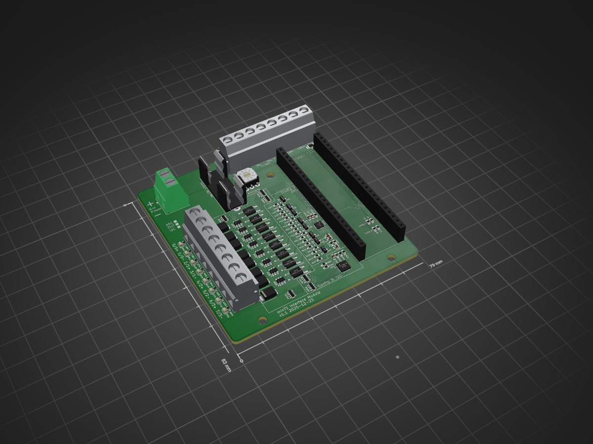
Interface module is an open-source printed circuit board by psas, from the psas/mints-scada-hardware repository on GitHub. It is a 2-layer board of 79 × 83 mm with 113 parts on 108 nets, routed with 777 tracks and 211 vias.
It is built around the MCP3464-E/NC, TCA9548ARGERQ1 and RMCF0603FT4K70, with the 1SS396,LF, SMBJ5360B-TP and B1911USD-20D000114U1930 among its other parts. Its parts include 45 resistors, 24 diodes, 11 ICs, 8 transistors and 7 capacitors. It belongs with the interfaces and adapters boards of this library.


Minimal Test Stand Supervisory Control and Data Acquisition system hardware and firmware. See mints-scada-software for the computer software to control the whole system.
Firmware files are located in the firmware/bin directory.
Command line firmware flashing instructions are provided for Ubuntu 24.04. Other debian-based Linux distros should follow a similar procedure. Flashing from Mac or Windows should be possible, but is not covered here.
dfu-util with sudo apt install dfu-util/etc/udev/rules.d/60-stm32# STM32
ACTION=="add", SUBSYSTEM=="usb", ATTRS{idVendor}=="0483", ATTRS{idProduct}=="df11", TAG+="uaccess"sudo udevadm control --reload-rules && sudo udevadm trigger to reload the udev rulesBOOT button while plugging it inRESET and BOOT, then release RESET then BOOTdfu-util --list and confirm that there are two devices with the vendor:product ID 0483:df11, one with the name @Option Bytes and one with the name @Internal Flash. If any other devices with that ID are present, remove them before continuing.dfu-util --device 0483:df11 --alt 0 --dfuse-address 0x08000000:leave --download [path/to/file/]<filename>.bin. It should erase the flash, then download the new file and show File downloaded successfully when it is done.STM32CubeProgrammer can be used to flash device firmware. Setup will be platform-dependent, and thusly not covered here.
To build and upload:
PROJECT TASKS > Build > General execute the Build procedure by clicking on itUpload to upload to the microcontroller. Ensure that only a single board is plugged in to ensure you are writing to the correct device.Building firmware from source shouldn't be needed unless you are making changes to it. Firmware build instructions are provided for Ubuntu 24.04. Other debian-based Linux distros should follow a similar procedure. Flashing from Mac or Windows should be possible, but is not covered here.
You will need:
sudo apt install gcc-arm-none-eabisudo apt install makeTo build the code, simply run make in the firmware folder. This will build the firmware and copy the .bin into the firmware folder. Running make flash will build the firmware then upload it to a connected DFU mode microcontroller.
Initialization code was generated using [https://www.st.com/en/development-tools/stm32cubemx.html](STM32Cube initialization code generator). You should not need to mofidy this, but if you do, the module_io.ioc is included. If you regenerate the code, you may have to add
#######################################
# Flash
#######################################
flash: all
	dfu-util --device 0483:df11 --alt 0 --dfuse-address 0x08000000:leave --download $(BUILD_DIR)/$(TARGET).bin
to the end of Makefile. Optionally, add cp $(BUILD_DIR)/$(TARGET).bin $(TARGET).bin to target all in the makefile (add line 171) to copy the bin out of the build direcotry. Generally, CubeMX does not seem to update the Makefile if it exists.
assembly sections. Do not populate THT components yetGND 3v3, and GND and either pad of the polyfuse (the component in the corner of the board by the USB port). Verify there are no shorts.sudo dmesg -Hw to monitor system messages in real time (-m) with human-readable timestamps (-h). Keep this window open and visible for the next stepdmesg. The following should appear. If it does not, then there is a problem with your board.[<starttime>] usb 3-2: new full-speed USB device number <id> using xhci_hcd
[ +0.148877] usb 3-2: New USB device found, idVendor=0483, idProduct=df11, bcdDevice=22.00
[ +0.000014] usb 3-2: New USB device strings: Mfr=1, Product=2, SerialNumber=3
[ +0.000006] usb 3-2: Product: STM32 BOOTLOADER
[ +0.000006] usb 3-2: Manufacturer: STMicroelectronics
[ +0.000005] usb 3-2: SerialNumber: FFFFFFFEFFFFblink-fast.bin firmware. Confirm that the LED blinks at about 10Hz.blink-slow.bin firmware. Confirm that the LED blinks at about 1Hz. This confirms that you are able to flash new firmware to the device.blink-fast.bin and blink-slow.bin should already be built in the firmware/bin directory. If they are not, they can be rebuilt with the blink project. To rebuild them, run the following in firmware/blink
make clean && make DELAY=500 && cp blink.bin ../bin/blink-slow.bin
make clean && make DELAY=50 && cp blink.bin ../bin/blink-fast.bin| Qty | Value | Footprint | References |
|---|---|---|---|
| 10 | 4k7 | Resistor_SMD:R_0603_1608Metric | R201, R202, R203, R204, R205, R206, R207, R208, R304, R305 |
| 8 | 140357145200 | Package_SO:SO-4_4.4x3.6mm_P2.54mm | U201, U202, U203, U204, U205, U206, U207, U208 |
| 8 | 1SS396 | Package_TO_SOT_SMD:SOT-23 | D101, D102, D103, D104, D105, D106, D107, D108 |
| 8 | DMP3050LVT-7 | Package_TO_SOT_SMD:TSOT-23-6 | Q201, Q202, Q203, Q204, Q205, Q206, Q207, Q208 |
| 8 | SMBJ5360B-TP | Diode_SMD:D_SMB | D201, D202, D203, D204, D213, D214, D215, D216 |
| 8 | red | LED_SMD:LED_0603_1608Metric | D205, D206, D207, D208, D209, D210, D211, D212 |
| 6 | 0 | Resistor_SMD:R_0603_1608Metric | R102, R103, R301, R302, R303, R328 |
| 4 | 1u | Capacitor_SMD:C_0603_1608Metric | C101, C103, C104, C301 |
| 4 | R_ADC_BTM | Resistor_SMD:R_0603_1608Metric | R106, R110, R114, R118 |
| 4 | R_ADC_NEG | Resistor_SMD:R_0603_1608Metric | R107, R111, R115, R119 |
| 4 | R_ADC_POS | Resistor_SMD:R_0603_1608Metric | R105, R109, R113, R117 |
| 4 | R_ADC_TOP | Resistor_SMD:R_0603_1608Metric | R104, R108, R112, R116 |
| 4 | R_BIAS | Resistor_SMD:R_0603_1608Metric | R124, R125, R126, R127 |
| 4 | R_SHUNT | Resistor_SMD:R_0603_1608Metric | R120, R121, R122, R123 |
| 2 | 10k | Resistor_SMD:R_0603_1608Metric | R1, R3 |
| 2 | 10u | Capacitor_SMD:C_0603_1608Metric | C102, C105 |
| 2 | 330 | Resistor_SMD:R_Array_Convex_4x0603 | RN201, RN202 |
| 2 | 4k7 | Resistor_SMD:R_Array_Convex_4x0603 | RN301, RN302 |
| 2 | 5k1 | Resistor_SMD:R_Array_Convex_4x0603 | RN203, RN204 |
| 2 | Conn_01x08 | footprints:TerminalBlock_CUI-8_P5.08mm | J1, J2 |
| 1 | 0.1u | Capacitor_SMD:C_0603_1608Metric | C106 |
| 1 | 1 | Resistor_SMD:R_0603_1608Metric | R101 |
| 1 | 150mA Poly | Fuse:Fuse_1206_3216Metric | F301 |
| 1 | 15A slow | Fuse:Fuseholder_Cylinder-5x20mm_Schurter_0031_8201_Horizontal_Open | F201 |
| 1 | 350mA Poly | Fuse:Fuse_1206_3216Metric | F2 |
| 1 | Conn_01x02 | TerminalBlock_Phoenix:TerminalBlock_Phoenix_MKDS-1,5-2-5.08_1x02_P5.08mm_Horizontal | J3 |
| 1 | INFO1 | Resistor_SMD:R_0603_1608Metric | R2 |
| 1 | INFO2 | Resistor_SMD:R_0603_1608Metric | R4 |
| 1 | MCP3464 | Package_DFN_QFN:UQFN-20-1EP_3x3mm_P0.4mm_EP1.85x1.85mm | U101 |
| 1 | SW_Coded_SH-7050 | Button_Switch_THT:Nidec_Copal_SH-7010C | SW1 |
| 1 | TCA9548 | Package_DFN_QFN:Texas_RGE0024C_VQFN-24-1EP_4x4mm_P0.5mm_EP2.1x2.1mm | U301 |
| 1 | TestPoint | TestPoint:TestPoint_Pad_D1.0mm | TP201 |
| 1 | ~ | footprints:stm32dev | U1 |
The 109 most common of 113 parts.
It measures 79 × 83 mm and has 2 copper layers, 1.6 mm thick.
113 parts, built around the MCP3464-E/NC, TCA9548ARGERQ1, RMCF0603FT4K70 and 1SS396,LF. The full list of its parts is on this page, with links to each part's symbol and footprint where PCBKit's library has them.
From the psas/mints-scada-hardware repository on GitHub, at the commit this page was made from: the board is interface-module/interface-module.kicad_pcb and its schematic interface-module/config1_adc.kicad_sch. PCBKit opens the board in the browser, with nothing to install.
Its repository states no licence, so its author keeps all rights: ask psas before reusing the design.

Guiimartinho/open-power-profiler
Open-source PPK2-class power profiler built on the Raspberry Pi Pico 2: 100 kSPS, 100 nA to 1 A auto-ranging, source meter and ampere meter modes, USB stream.


oresat/oresat-c3-hardware
C3 (Command, Communication, and Control) our Command and Data Handling (C&DH) card.

oresat/oresat-dxwifi-hardware
OreSat hardware for high speed data communications using 2.4 GHz WiFi.

oresat/oresat-cfc-hardware
Cirrrus Flux Camera hardware repository


oresat/oresat-adcs-hardware
Controller PCB for OreSat reaction wheels, magnetorquers, IMU, and magnetometers