2 layers97.5 × 79 mm
RGB LED Driver
PCB-Design-MIT/Wi-Fi-Controlled-RGB-Light
A demo board for students to learn to solder and debug
144 parts4

 psas/liquid-engine-test-stand59
A small liquid rocket engine test stand.
Thermocouple is an open-source printed circuit board by psas, from the psas/liquid-engine-test-stand repository on GitHub, published under the GPL-2.0 licence. It is a 4-layer board of 94.7 × 73.7 mm with 117 parts on 105 nets, routed with 1,061 tracks and 111 vias.
It is built around the LM358DR and LTC3260IDE. Its parts include 59 resistors, 42 capacitors, 10 ICs and 2 connectors.

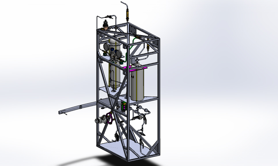
PSAS team members have already designed and built a 2.5 kN regeneratively cooled bipropellant (liquid oxygen and ethanol) rocket engine. This engine design included a number of innovative features including fully parametric CAD design using python scripts and SolidWorks, direct metal laser sintering (DMLS) additive manufacturing by i3D manufacturing, direct spark ignition and pintle injection. Although the rocket engine itself has already been produced, much of the overall system complexity lies in the piping, control, and data acquisition systems which support it. This project intends to flesh out these systems in order to test the engine and its successors.
The test stand will safely test current and PSAS future generation liquid fuel engines prior to integration into a flight vehicle. PSAS will use the stand to measure engine performance, liquid fuel and oxidizer flow rates, propellant mixing capabilities and other engine performance figures of merit. These tests will be performed remotely, using automated valve switching and data acquisition systems. The LFETS system is designed to be portable by truck, and will support propulsion testing of engines up to 10 kN of thrust. The project will be open-source and will utilize live web-based Jupyter notebook design documentation.
The feed system uses a classic regulated pressure-fed thermodynamic cycle. Gaseous nitrogen is the pressurant. The LFETS system includes a welded thrust loading truss structure, propellant and pressurant supply tanks, and feed system flow componentry. The project also includes safety and Failure Mode Effects Analysis, and procedures for safe operation and transport. The LFETS Electrical Ground Support Equipment (EGSE) will allow for the test stand to be controlled remotely. The test stand computer controls all actuators in the LFETS system, auto-sequences engine ignition, start, shutdown, pad-safing, and contingency procedures for any test exception, as well as receiving telemetry from sensors and instrumentation. The LFETS EGSE system is derived from the 3rd generation PSAS launch tower computer, which uses a BeagleBone Black microcontroller, the Marionette open-source DAQ, and a custom “SCADA-like” GUI.
| Qty | Value | Footprint | References |
|---|---|---|---|
| 16 | 0 | Resistors_SMD:R_0805_HandSoldering | R38, R39, R40, R41, R44, R45, R46, R47, R48, R50, R52, R54, R55, R56, R57, R58 |
| 15 | .1uF | Capacitors_SMD:C_0402 | C8, C24, C25, C26, C27, C28, C29, C30, C31, C32, C33, C38, C39, C41, C42 |
| 12 | 100 | Resistors_SMD:R_1206 | R10, R11, R12, R13, R14, R15, R16, R17, R30, R31, R32, R33 |
| 10 | .01uF | Capacitors_SMD:C_0402 | C3, C5, C15, C16, C17, C18, C19, C20, C21, C22 |
| 9 | 1uF | Capacitors_SMD:C_0603_HandSoldering | C4, C11, C12, C13, C14, C34, C35, C36, C37 |
| 7 | 10uF | Capacitors_SMD:C_0603_HandSoldering | C1, C2, C6, C7, C10, C23, C40 |
| 4 | 10K | Resistors_SMD:R_0603_HandSoldering | R18, R19, R20, R21 |
| 4 | 178 | Resistors_SMD:R_0402 | R49, R51, R53, R59 |
| 4 | 1M | Resistors_SMD:R_0805_HandSoldering | R6, R7, R8, R9 |
| 4 | 3.32K | Resistors_SMD:R_0805_HandSoldering | R22, R23, R24, R25 |
| 4 | 5K | Resistors_SMD:R_1206 | R26, R27, R28, R29 |
| 4 | AD8495 | snapEda:SOP65P490X110-8N | U3, U4, U5, U6 |
| 4 | MountingHole_2.7mm_M2.5_Pad_Via | Mounting_Holes:MountingHole_2.7mm_M2.5_Pad_Via | REF1, REF2, REF3, REF4 |
| 2 | 221K | Resistors_SMD:R_0805_HandSoldering | R2, R5 |
| 2 | 30.1K | Resistors_SMD:R_0805_HandSoldering | R1, R4 |
| 2 | MCP3424T-E/ST | snapEda:SOP65P640X120-14N | U8, U10 |
| 1 | 1.3K | Resistors_SMD:R_0603_HandSoldering | R43 |
| 1 | 10.2K | Resistors_SMD:R_0805_HandSoldering | R35 |
| 1 | 11.1K | Resistors_SMD:R_0603_HandSoldering | R36 |
| 1 | 2.2uF | Capacitors_SMD:C_0805_HandSoldering | C9 |
| 1 | 2.55K | Resistors_SMD:R_0402 | R37 |
| 1 | 200K | Resistors_SMD:R_0805_HandSoldering | R3 |
| 1 | 4.75K | Resistors_SMD:R_0805_HandSoldering | R42 |
| 1 | 5.17K | Resistors_SMD:R_0603_HandSoldering | R34 |
| 1 | ADA4062 | snapEda:ADA4062-4ARUZ | U7 |
| 1 | CONN_02X13 | Pin_Headers:Pin_Header_Straight_2x13 | P1 |
| 1 | DB25 | snapEda:TE_Conn_5747846_4_DB25 | J1 |
| 1 | LM358DR | digikey-footprints:SOIC-8_W3.9mm | U9 |
| 1 | LM78L05ACZ_NOPB | digikey-footprints:TO-92-3 | U2 |
| 1 | LTC3260 | snapEda:MSOP-16_MSE | U1 |
It measures 94.7 × 73.7 mm and has 4 copper layers, 1.6 mm thick.
117 parts, built around the LM358DR and LTC3260IDE. The full list of its parts is on this page, with links to each part's symbol and footprint where PCBKit's library has them.
From the psas/liquid-engine-test-stand repository on GitHub, at the commit this page was made from: the board is TSAR/TSAR_ADC/kicad_board_design/thermocouple.kicad_pcb. PCBKit opens the board in the browser, with nothing to install.
Its repository publishes it under the GPL-2.0 licence: you may reuse it on that licence's terms (keep the author's notice, and for a copyleft licence share your changes alike).
PCB-Design-MIT/Wi-Fi-Controlled-RGB-Light
A demo board for students to learn to solder and debug

ArduProject/PCB_DRONE_C8
En este repositorio encontrareis los archivos de fabricación y las listas de montaje del PCB con STM32F103C8 que hemos visto en el curso.


paulmartinezcuenta/Proyecto_finales_mecatronica_ITLA
Monorepo for two mechatronics projects sharing a panelized PCB: HydroScan (autonomous IoT maritime buoy with LTE, GPS, and solar power) and AUTOAMBU (automated medical respirator prototype with DC control and USB fast…

paulmartinezcuenta/UltiCore-V1-PLC
Custom industrial-grade PLC and logic controller engineered around the ESP32 platform.


A1DS19/drone-flight-controller
A custom drone flight controller, designed in KiCad 10: an STM32F103R8T6 flight core paired with an ATmega328P telemetry co-processor on a four-layer, 102 × 49 mm PCB — taken from schematic capture through placement…