
4 layers36 × 50.2 mm
Racer
StuckAtPrototype/Racer
These are structured into their own files. I could have used submodules, but decided against it.
83 parts3.8kApache-2.0
 pryre/robin
A real-time offboard flight controller for low level interfacing in ROS
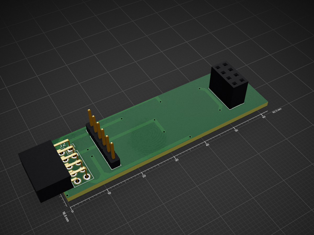
Esp wifi adapter is an open-source printed circuit board by pryre, from the pryre/robin repository on GitHub, published under the GPL-3.0 licence. It is a 2-layer board with 11 parts on 17 nets, routed with 89 tracks and 10 vias.
It is built around the BSS138. Its parts include 5 resistors, 3 connectors, 2 transistors and 1 IC. It belongs with the radio and wireless and interfaces and adapters boards of this library.
The ROS Offboard Integration for Naze32-based flight controllers.
Additional documentation on features, interfacing, and packaged tools, please check here (/documents/README.md).
Pre-compiled releases can be found in Releases section. Make sure to get the correct release revision for your board model.
A binary of stm32flash can be found on the official repository. Download and extract stm32flash.exe to a folder of your choice.
You can not only pass the version flag in the command line, but you can also pass the serial parameters to use as well:
make flash SERIAL_DEVICE=/dev/ttyACM0 SERIAL_BAUD=57600 NAZE32_REV=5Before you can flash the the Naze32, you must first put it into bootloader mode. For the initial flash, you must connect the bootloader pins while powering on the device. The location of the boot pins is detailed here.
Depending on your version of stm32flash, you may have to call the flash command multiple times before the flashing will actually start. If the flash is not successful, try using a slower baud rate, such as 115200. Another common problem is that stm32flash sometimes misses the initializer message from the autopilot if plugged in via USB, or it gets confused by other data in the serial buffer. The best work around for this is to do the following:
Use the following commands to flash the firmware to your flight controller. You will need to replace the filename (robin_naze32_revX.hex) and device name (/dev/ttyUSBX or COMX) with the correct options for your setup.
stm32flash -w robin_naze32_revX.hex -v -g 0x0 -b 921600 /dev/ttyUSBXCopy the firmware to the same folder as the one where you extracted stm32flash.exe. You can then Shift+Right Click and select Open Command Prompt Here.
In the command prompt, run the following:
./stm32flash.exe -w robin_naze32_revX.hex -v -g 0x0 -b 921600 COMXsudo apt install gcc-arm-none-eabi stm32flash python3-yaml
mkdir -p ~/src
cd ~/src
git clone --recursive https://github.com/qutas/robin/sudo pacman -S arm-none-eabi-gcc arm-none-eabi-newlib python-yamlYou'll also need to get the stm32flash package from the AUR or compile it manually
mkdir -p ~/src
cd ~/src
git clone --recursive https://github.com/qutas/robin/Compiling the source code is not currently possible on Windows, however it is still possible to flash the precompiled firmware.
cd ~/src/robin
make posix_udp
To compile for a differennt build target, such as naze32_rev5 or naze32_rev6, simply specify this instead:
make naze32_rev5You can list all primary build targets with the following command:
make list_targetsThe makefile assumes that the device is connected as /dev/ttyUSB0 and will use a baud rate of 921600. You may have to adjust these to suit your device.
Once in bootloader mode run the following command:
make naze32_rev5_flash SERIAL_DEVICE=/dev/ttyACM0 SERIAL_BAUD=57600After the initial flash, you can use the MAVLINK command MAV_CMD_PREFLIGHT_REBOOT_SHUTDOWN to put the device into bootloader mode through the software. Additionally, the following command will attempt to send this directly from the CLI (but requires pymavlink to be installed):
make naze32_rev5_reflash| Qty | Value | Footprint | References |
|---|---|---|---|
| 5 | 10K | Resistors_SMD:R_1206_HandSoldering | R1, R2, R3, R4, R5 |
| 2 | BSS138 | TO_SOT_Packages_SMD:SOT-23 | Q1, Q2 |
| 1 | CONN_01X06 | Socket_Strips:Socket_Strip_Straight_1x06_Pitch2.54mm | J3 |
| 1 | CONN_02X04 | Socket_Strips:Socket_Strip_Straight_2x04_Pitch2.54mm | J1 |
| 1 | CONN_02X05 | Socket_Strips:Socket_Strip_Straight_2x05_Pitch2.54mm | J2 |
| 1 | MCP1826S | TO_SOT_Packages_SMD:SOT-223 | U1 |
11 parts, built around the BSS138. The full list of its parts is on this page, with links to each part's symbol and footprint where PCBKit's library has them.
From the pryre/robin repository on GitHub, at the commit this page was made from: the board is hardware/wifi-adapter/esp-wifi-adapter.kicad_pcb. PCBKit opens the board in the browser, with nothing to install.
Its repository publishes it under the GPL-3.0 licence: you may reuse it on that licence's terms (keep the author's notice, and for a copyleft licence share your changes alike).
StuckAtPrototype/Racer
These are structured into their own files. I could have used submodules, but decided against it.

willem-pennings/balancing-cube
A cube that balances itself in a corner or edge using reaction wheels

abhishek-kakkar/BeagleLogic
A Software Suite that implements a logic analyzer with the PRU on the BeagleBone / BeagleBone Black.


lachlanA/eagle-to-kicad
Eagle SCH/LIB to KiCad SCH/LIB ULP conversion script

No0ne/ps2x2pico
USB keyboard/mouse to PS/2 interface converter using a Raspberry Pi Pico

StuckAtPrototype/AirCube
Works standalone out of the box. Pairs with Home Assistant in minutes. Other platforms are supported through community-contributed extensions.
