
4 layers36 × 50.2 mm
Racer
StuckAtPrototype/Racer
These are structured into their own files. I could have used submodules, but decided against it.
83 parts3.8kApache-2.0

 No0ne/ps2x2pico399
USB keyboard/mouse to PS/2 interface converter using a Raspberry Pi Pico
Ps2 pico hat is an open-source printed circuit board by No0ne, from the No0ne/ps2x2pico repository on GitHub, published under the MIT licence. It is a 2-layer board of 21.6 × 52.3 mm with 17 parts on 38 nets, routed with 115 tracks and 41 vias.
It is built around the BSS138. Its parts include 8 resistors, 4 transistors and 2 connectors. It belongs with the keyboards and input boards and the RP2040 boards of this library.
USB keyboard/mouse to PS/2 interface converter using a Raspberry Pi Pico
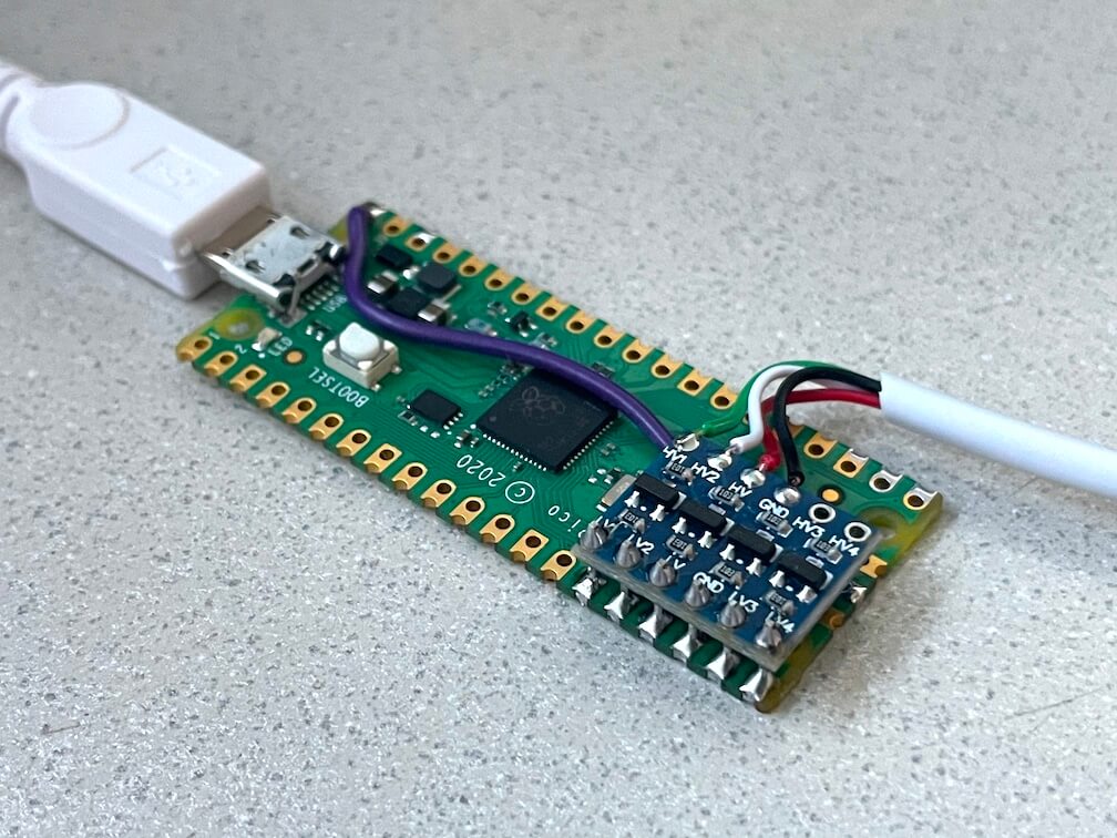 | 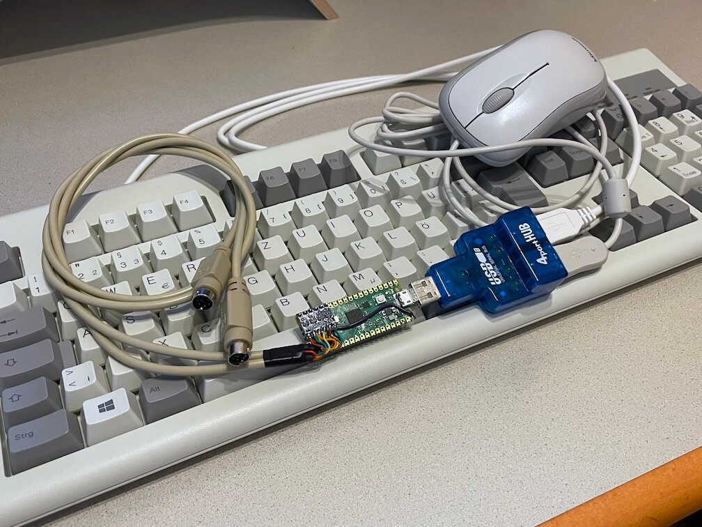 | 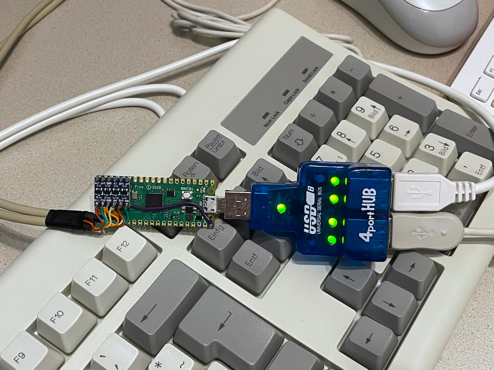 | 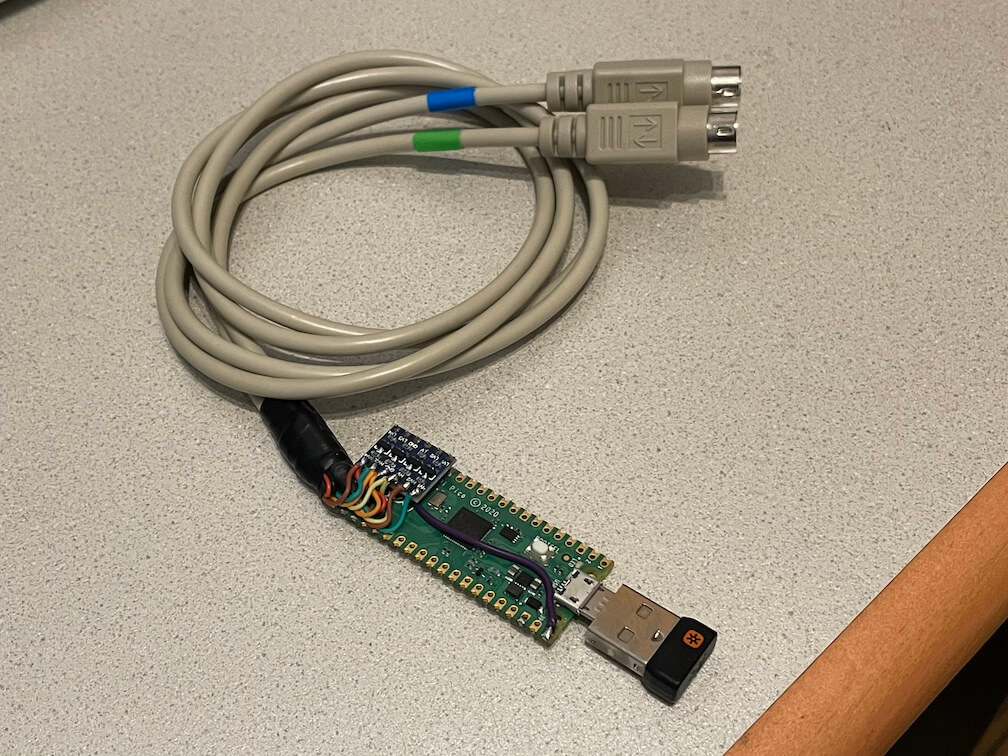 |
|---|
Keyboard only (incl. PC-XT) variant: https://github.com/No0ne/ps2pico
There is also an alternative ps2pico firmware for the PC-XT and ps2x2pico hardware: ps2pico-XT-alt.uf2
Additional excellent documentation by Ray: https://minuszerodegrees.net/keyboard/ps2x2pico.htm
PicoMiteVGA variant: https://github.com/No0ne/hid2cdc
PiKVM integration:
ITX-Llama integration: https://github.com/eivindbohler/itxllama
ps2x2pico.uf2 from https://github.com/No0ne/ps2x2pico/releasesps2x2pico.uf2 to your Pi Pico by pressing BOOTSEL before pluggging in.⚠️ Please note that some older motherboards have non-resettable fuses rated under 300mA.
Check the power consumption of your keyboard/mouse/hub first before plugging in!
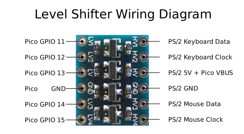
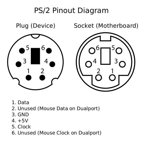
⚠️ Do not assume wire colors will match cables depicted in photos. Double-check your pinout with a multimeter.
If you also want to use a real PS/2 keyboard and mouse together with your USB devices you can mount another level shifter on top of the pico. These two ports work as PS/2 inputs and are passed through to the PS/2 output ports.
Don't forget to wire HV to 5V and your PS/2 sockets to power the connected PS/2 devices.
PS/2 passthru is especially useful with the PiKVM Pico HID or Pico HID Bridge as you can continue using your existing peripherals.
⚠️ Please note that the UF2 from PiKVM uses different GPIOs due to jumper pins:
Don't forget to wire LV to 3.3V and GND to GND separately as the level shifter does not fit directly on top of the pico.
You can hook up a USB serial adapter to GPIO0 for additional debugging output. The serial settings are 115200 baud, 8 data bits and no parity. You can also use another Pico running the pico-uart-bridge for this.
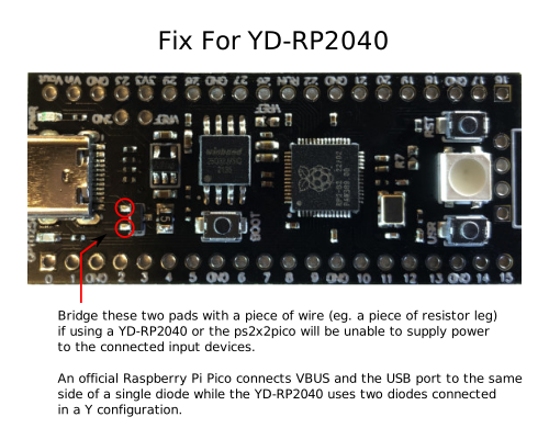
⚠️ If you have a YD-RP2040 (see silkscreen on back of board if unsure) and are not using a USB hub with its own power supply, you need to bridge two pads of the diode pair near the USB-C port as seen here:
Install needed libraries and tools:
sudo apt install cmake gcc-arm-none-eabi build-essential pkg-config libusb-1.0-0-dev libusb-1.0-0Get the Raspberry Pi Pico SDK version 1.5.1:
git clone https://github.com/raspberrypi/pico-sdk
export PICO_SDK_PATH=/path/to/pico-sdk
cd $PICO_SDK_PATH
git checkout 1.5.1
git submodule update --init
Update to the latest TinyUSB release 0.17.0:
cd $PICO_SDK_PATH/lib/tinyusb
git checkout 0.17.0
Generate the UF2 file:
cd /path/to/ps2x2pico
mkdir build
cd build
cmake ..
makeThere are two case versions for this project, one for the hat variant in freecad/ and one for the level shifter version in openscad/.
The case is snap fit and doesn't require any fasteners. You can print it as is using ps2x2pico_case.stl in your slicer but various customisation options are included in the underlying OpenSCAD model ps2x2pico_case.scad should you need them. This allows you to adjust tolerances or clearances of the height of the case and the various holes and support posts.
Note that when opening the case in OpenSCAD the BOSL2 library is required.
| Qty | Value | Footprint | References |
|---|---|---|---|
| 8 | 10K | Logic_Level_Bidirectional:0603-RES | R1, R2, R3, R4, R5, R6, R7, R8 |
| 4 | BSS138 | Logic_Level_Bidirectional:SOT23-3 | Q1, Q2, Q3, Q4 |
| 2 | OSHW-LOGOS | Logic_Level_Bidirectional:OSHW-LOGO-S | LOGO1, LOGO2 |
| 1 | Conn_01x20_Female_left | Connector_PinSocket_2.54mm:PinSocket_1x20_P2.54mm_Vertical | J1 |
| 1 | Conn_01x20_Female_right | Connector_PinSocket_2.54mm:PinSocket_1x20_P2.54mm_Vertical | J2 |
| 1 | Kycon-KMDGX-6S-BS | Library:KMDGX-6S-BS | Mini-DIN-6 |
It measures 21.6 × 52.3 mm and has 2 copper layers, 1.6 mm thick.
17 parts, built around the BSS138. The full list of its parts is on this page, with links to each part's symbol and footprint where PCBKit's library has them.
From the No0ne/ps2x2pico repository on GitHub, at the commit this page was made from: the board is kicad/ps2_pico_hat.kicad_pcb and its schematic kicad/ps2_pico_hat.kicad_sch. PCBKit opens the board in the browser, with nothing to install.
Its repository publishes it under the MIT licence: you may reuse it on that licence's terms (keep the author's notice, and for a copyleft licence share your changes alike).
StuckAtPrototype/Racer
These are structured into their own files. I could have used submodules, but decided against it.

willem-pennings/balancing-cube
A cube that balances itself in a corner or edge using reaction wheels

abhishek-kakkar/BeagleLogic
A Software Suite that implements a logic analyzer with the PRU on the BeagleBone / BeagleBone Black.


lachlanA/eagle-to-kicad
Eagle SCH/LIB to KiCad SCH/LIB ULP conversion script

StuckAtPrototype/AirCube
Works standalone out of the box. Pairs with Home Assistant in minutes. Other platforms are supported through community-contributed extensions.

