
4 layers81 × 81.3 mm
Dac ng
prydin/toy-dac
A 1-bit ΔΣ stereo audio DAC implemented on a Xilinx 7-series FPGA (Digilent Cmod S7), driven from an I²S input.
86 parts4

 prydin/toy-dac4
A 1-bit ΔΣ stereo audio DAC implemented on a Xilinx 7-series FPGA (Digilent Cmod S7), driven from an I²S input.
Clock is an open-source printed circuit board by prydin, from the prydin/toy-dac repository on GitHub. It is a 2-layer board of 24.1 × 21 mm with 7 parts on 9 nets, routed with 34 tracks and 39 vias.
It is built around the C3391-22.5792 and C3391-24.576. Its parts include 2 capacitors, 2 diodes, 2 crystals and 1 connector. It belongs with the lEDs and displays boards of this library.
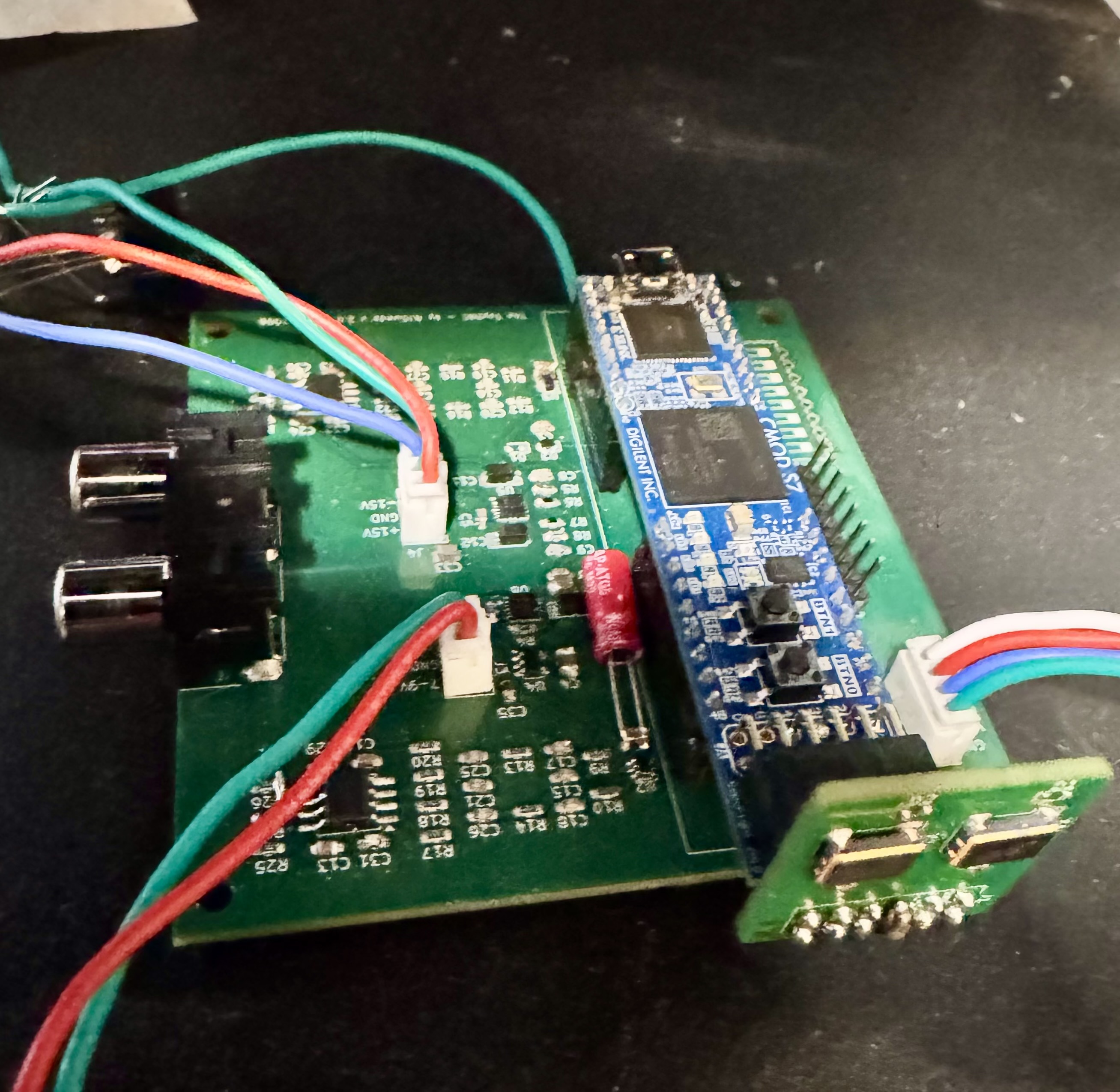
toy-dac started as a challenge: make a DAC that could at least produce sound. It has grown well beyond that proof of concept into a working DAC that reproduces music very nicely. The name is a nod to those humble beginnings, not a measure of what the project can do today.
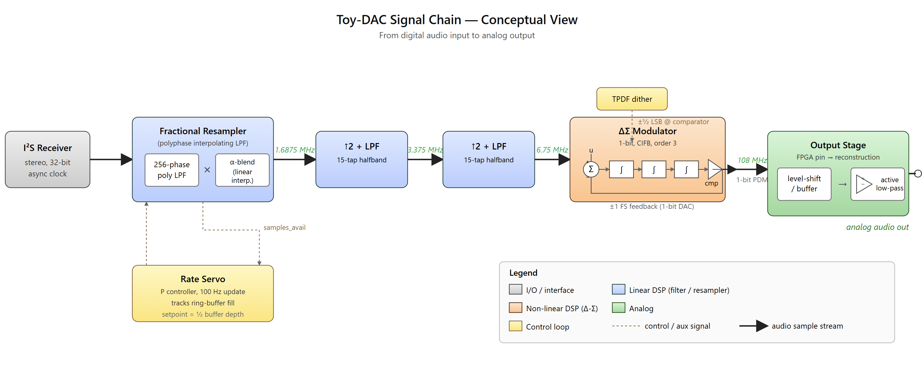
A 1-bit ΔΣ stereo audio DAC implemented on a Xilinx 7-series FPGA (Digilent Cmod S7), driven from an I²S input.
The signal chain is entirely made-from-scratch RTL:
Internal test sources (silent, DC, 1 kHz DDS sine) and a bypass mode (raw I²S → modulator) are included for bring-up and characterisation.
The current build is surpassing 90 dB SNR. The remaining distortion is mainly the second and third harmonics (H2 and H3), which we believe are related to the DAC's switching output. Extensive listening tests have found it almost on par with commercial DACs, though there is still work to do on the finer details.
First viable version. toy-dac has grown from a proof of concept into a working DAC capable of reproducing music very nicely. It has been exercised on hardware and through extensive listening tests, but is still evolving: the analog board is a hand-routed prototype, the design has not had formal verification, and there is more work to do on measured performance and subjective refinement. Module ports, parameter names, and pinouts may change without notice; treat it as an evolving project rather than drop-in IP.
fpga/toy-dac/   Vivado project (RTL under src/rtl, constraints under
                toy-dac.srcs/constrs_1, simulation under toy-dac.srcs/sim_1)
kicad/dac/      KiCad schematic + PCB for the analog carrier board
scripts/        Coefficient generation, simulation helpers, sanity checks
docs/ Block diagrams (top-level + ASRC internals)Open fpga/toy-dac/toy-dac.xpr in Vivado 2024.2, run synthesis +
implementation + bitstream generation, and program the Cmod S7. The
target part and pin assignments live in
fpga/toy-dac/toy-dac.srcs/constrs_1/new/root.xdc.
| Qty | Value | Footprint | References |
|---|---|---|---|
| 2 | 100n | Capacitor_SMD:C_0603_1608Metric_Pad1.08x0.95mm_HandSolder | C1, C2 |
| 2 | LED | LED_SMD:LED_0603_1608Metric | D1, D2 |
| 1 | C3391-22.5792 | Oscillator:Oscillator_SMD_Diodes_FN-4Pin_7.0x5.0mm | Y1 |
| 1 | C3391-24.576 | Oscillator:Oscillator_SMD_Diodes_FN-4Pin_7.0x5.0mm | Y2 |
| 1 | Conn_02x06_Top_Bottom | Connector_PinHeader_2.54mm:PinHeader_2x06_P2.54mm_Vertical | J1 |
prydin/toy-dac
A 1-bit ΔΣ stereo audio DAC implemented on a Xilinx 7-series FPGA (Digilent Cmod S7), driven from an I²S input.

prydin/toy-dac
A 1-bit ΔΣ stereo audio DAC implemented on a Xilinx 7-series FPGA (Digilent Cmod S7), driven from an I²S input.


byrantech/laptop
anyon_e, a highly integrated, high end, open source laptop. Attempt the impossible.


AxxAxx/AxxSolder
STM32 Based soldering station for JBC cartridges, 9-24 VDC and USB-PD power


jamro/tiny-engineer
A small desktop robot that brings an AI coding assistant to life, physically acting out when it reads files, thinks, writes code, and finishes work.

hoglet67/RGBtoHDMI
Bare-metal Raspberry Pi project that provides pixel-perfect sampling of Retro Computer RGB/YUV video and conversion to HDMI
It measures 24.1 × 21 mm and has 2 copper layers, 1.6 mm thick.
7 parts, built around the C3391-22.5792 and C3391-24.576. The full list of its parts is on this page, with links to each part's symbol and footprint where PCBKit's library has them.
From the prydin/toy-dac repository on GitHub, at the commit this page was made from: the board is kicad/dac-ng/clock/clock.kicad_pcb and its schematic kicad/dac-ng/clock/clock.kicad_sch. PCBKit opens the board in the browser, with nothing to install.
Its repository states no licence, so its author keeps all rights: ask prydin before reusing the design.