
2 layers88.5 × 74.5 mm

 prydin/param-eq3
Parametric Equalizer
Regulator is an open-source printed circuit board by prydin, from the prydin/param-eq repository on GitHub. It is a 2-layer board of 56.5 × 47.2 mm with 32 parts on 12 nets, routed with 74 tracks and 0 vias.
It is built around the R-78C5.0-1.0. Its parts include 10 capacitors, 6 resistors, 4 ICs, 4 connectors and 2 inductors. It belongs with the power boards of this library.
This project started as a focused experiment: build a practical, hardware-controlled parametric equalizer. Along the way it grew into something broader: a general-purpose DSP platform for real-time audio processing, instrumentation, and UI experiments.
What began as "just three EQ bands" now includes filter control, combined response visualization, VU metering, spectrum visualization, and a register-based control/data protocol between two MCUs.
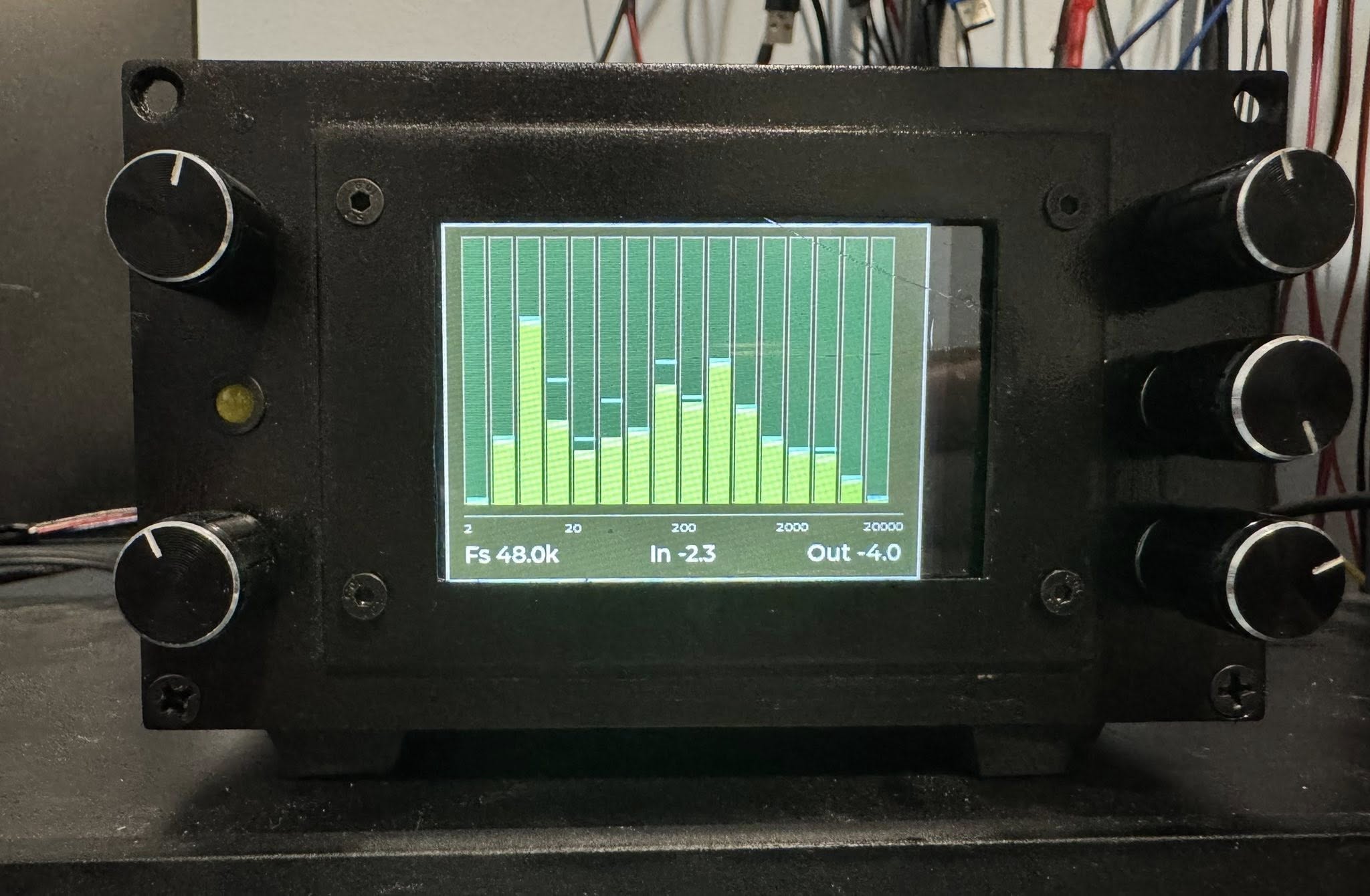

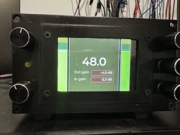
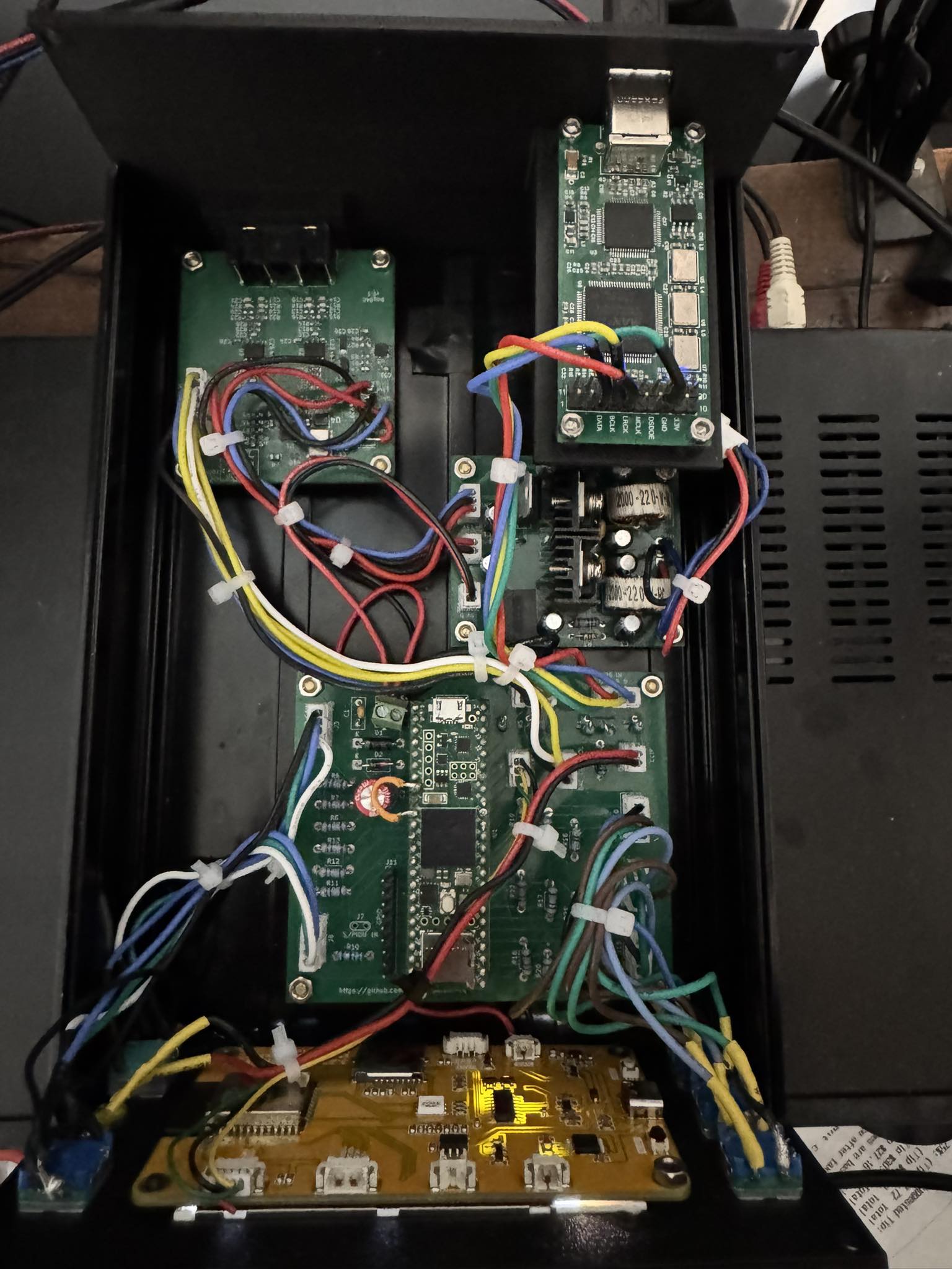
The original goal was simple:
That third point changed everything. Once the DSP core and UI link were stable, it became obvious that the architecture could do far more than EQ alone. The codebase now behaves more like a modular DSP workbench than a single-purpose effect.
The system uses two processors, each doing the job it is best at.
Why Teensy 4.1:
The UI runs on a CYD (Cheap Yellow Display), which is an ESP32-based board with an integrated TFT.
Communication between DSP and UI uses compact register messages over I2C.
The UI currently provides three main modes, each optimized for a different use case.
Purpose: precise tuning and analysis.
Purpose: quick operating view.
Purpose: visualize real-time spectral behavior.
When operating in Simple or Spectrum mode, parameter changes can trigger a framed popup showing key filter settings (band, type, frequency, gain, and Q). The popup auto-hides after inactivity, and can be gated by user-input state so remote/background updates do not constantly interrupt the view.
Long term, the plan is to fold this work into a DAC/DSP/preamplifier build. This repository is the proving ground for that hardware/software stack.
Big thanks to the diyAudio.com community.
Many design choices, implementation refinements, and troubleshooting ideas were inspired by the knowledge shared by diyAudio members. The project benefited directly from their practical guidance, experience, and generosity in public discussion threads.
| Qty | Value | Footprint | References |
|---|---|---|---|
| 4 | 10u | Capacitor_THT:CP_Radial_D4.0mm_P1.50mm | C3, C4, C5, C6 |
| 4 | 4.7u | Capacitor_THT:CP_Radial_D4.0mm_P1.50mm | C1, C2, C7, C8 |
| 4 | MountingHole | MountingHole:MountingHole_3.2mm_M3 | H1, H2, H3, H4 |
| 3 | 220 | Resistor_THT:R_Axial_DIN0204_L3.6mm_D1.6mm_P7.62mm_Horizontal | R1, R3, R6 |
| 2 | 100n | Capacitor_THT:C_Disc_D4.3mm_W1.9mm_P5.00mm | C9, C10 |
| 2 | 2.2k | Resistor_THT:R_Axial_DIN0204_L3.6mm_D1.6mm_P7.62mm_Horizontal | R4, R5 |
| 2 | 22u | Inductor_THT:L_Toroid_Vertical_L17.8mm_W8.1mm_P7.62mm_Bourns_5700 | L1, L2 |
| 2 | LM317_TO-220 | Package_TO_SOT_THT:TO-220-3_Vertical | U1, U3 |
| 1 | +-15V | Connector_JST:JST_PH_B3B-PH-K_1x03_P2.00mm_Vertical | J2 |
| 1 | 5V Analog | Connector_JST:JST_PH_B2B-PH-K_1x02_P2.00mm_Vertical | J1 |
| 1 | 5V Digital | Connector_JST:JST_PH_B2B-PH-K_1x02_P2.00mm_Vertical | J3 |
| 1 | 680 | Resistor_THT:R_Axial_DIN0204_L3.6mm_D1.6mm_P7.62mm_Horizontal | R2 |
| 1 | AC | TerminalBlock_Phoenix:TerminalBlock_Phoenix_MPT-0,5-3-2.54_1x03_P2.54mm_Horizontal | J4 |
| 1 | LM337_TO220 | Package_TO_SOT_THT:TO-220-3_Vertical | U4 |
| 1 | R-78C5.0-1.0 | Converter_DCDC:Converter_DCDC_RECOM_R-78E-0.5_THT | U2 |
The 30 most common of 32 parts.
It measures 56.5 × 47.2 mm and has 2 copper layers, 1.6 mm thick.
32 parts, built around the R-78C5.0-1.0. The full list of its parts is on this page, with links to each part's symbol and footprint where PCBKit's library has them.
From the prydin/param-eq repository on GitHub, at the commit this page was made from: the board is kicad/regulator/regulator.kicad_pcb and its schematic kicad/dac/dac.kicad_sch. PCBKit opens the board in the browser, with nothing to install.
Its repository states no licence, so its author keeps all rights: ask prydin before reusing the design.


plan44/p44ttngw-hardware
KiCAD files for TTN LoRA gateway based on RAK831 and Omega2S

fablab-wue/piTelex.supplement
This project hold the additional files for the teletype project piTelex

ImogenWren/i2c-arduino-daq
Arduino interface for i2c sensors with Serial CSV output for use with Data Aquisition Software


3stan-H/Bench-Power-Supply
A mains-powered, adjustable bench power supply designed in KiCad, converting 120V AC wall input into a regulated 1–20V DC output.

AssociationRobotTelecomStrasbourg/CarteM-re1A2A-CFR2020
Carte-mère du robot 1A2A pour la CFR2020