
4 layers82.6 × 58.4 mm

BogDAC - A no-frills ES9039Q2M DAC board
Dac is an open-source printed circuit board by prydin, from the prydin/bogdac repository on GitHub. It is a 4-layer board of 54.5 × 61.3 mm with 87 parts on 49 nets, routed with 463 tracks and 224 vias.
It is built around the ES9039Q2M, LT3046ATC+ and CE3391-49.152. Its parts include 32 capacitors, 32 resistors, 5 ICs, 5 connectors and 1 crystal. It belongs with the audio and music boards of this library.

I like to keep things simple. Reading about people "improving" their DACs with femtosecond-precision clocks, re-clockers, hundreds of farads of capacitance and potting soil (yes, potting soil), I decided I wanted to create a bog standard DAC board based on the ES9039Q2M chip. I wanted a small board that would just accept an I2S stream and I2C commands and output single-ended audio.
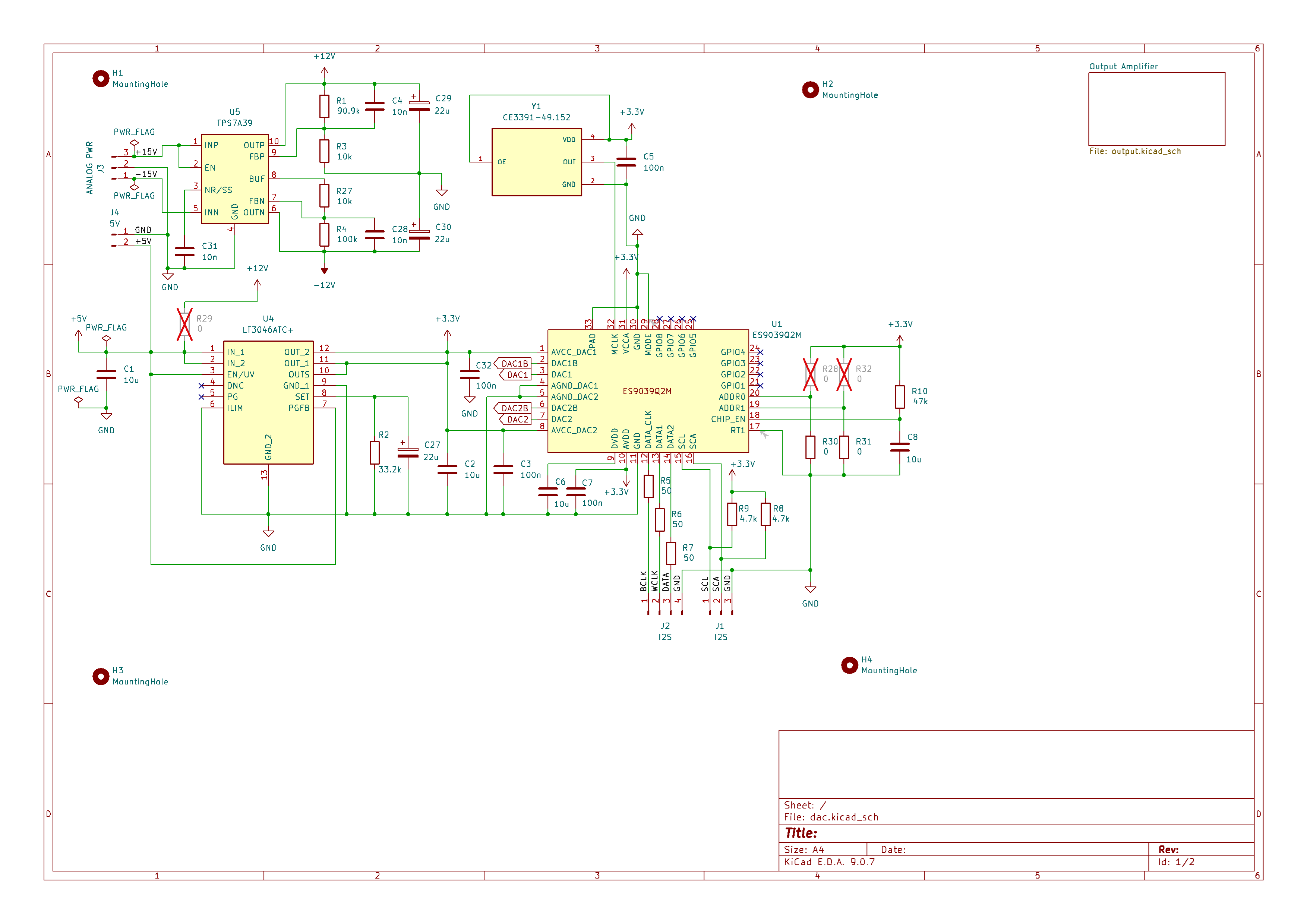
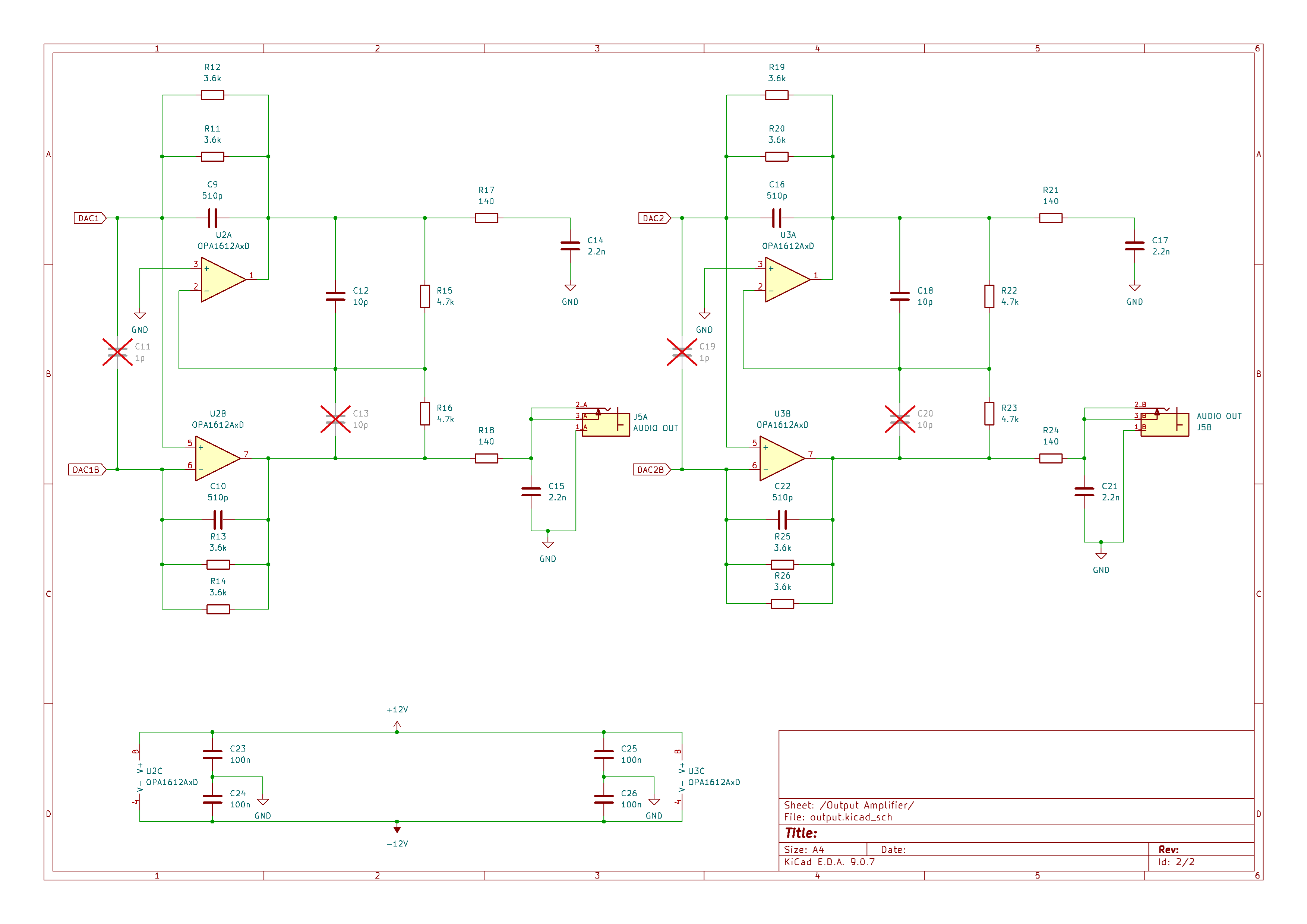
This is following my Bog Standard concept: Keep things simple, follow best practices and avoid audiophile fads. The chip is locked into software mode and asynchronous I2S (a.k.a. PCM) operations using a local 49.152MHz oscillator. This allows for a design with a very simple and short clock signal path and should (at least in my opinion) perform better than external clocks connected through wires. The output section is pretty much just the one suggested in the data sheet and based on OPA1612. The +/- 12V power for the analog section is provided by a TPS7A39 regulator. The 3.3V power for the analog reference voltages and the digital power is fed by a LT3046 regulator. The L3046 can be fed either from a separate 5V power input or from the 12V rail by installing a jumper. Please note that nothing should be plugged into the 5V inlet if the jumper is installed.
I tested this using a QA403. While this is a superb piece of gear, it has its limitations compared to test equipment that costs 100 times more. Because of this, the lower bound of the THD I can measure is about 0.0001% and the lowest noise floor is just above -150dBV. In fact, the harmonic profile of a loopback measurement looks very similar to the results I'm getting, so my hypothesis is that almost all noise and distortion you see comes from the measurement setup and not the circuit.
A 1kHz tone at full volume yields this spectrum. The THD is about 0.00013# and the SNR sits at about 113dB. I think the actual numbers are a lot better. Anyone who wants to lend me a $50,000 audio analyzer? :)
Another interesting measurement is looking at the idle noise. This is the DAC fully enabled, but without an input signal. I'm running the board on a cheap lab supply. As you can see, there's virtually no hum and very low noise.
You can thank those fancy regulators for that!
| Qty | Value | Footprint | References |
|---|---|---|---|
| 8 | 3.6k | Resistor_SMD:R_0603_1608Metric_Pad0.98x0.95mm_HandSolder | R11, R12, R13, R14, R19, R20, R25, R26 |
| 6 | 4.7k | Resistor_SMD:R_0603_1608Metric_Pad0.98x0.95mm_HandSolder | R8, R9, R15, R16, R22, R23 |
| 5 | 0 | Resistor_SMD:R_0603_1608Metric_Pad0.98x0.95mm_HandSolder | R28, R29, R30, R31, R32 |
| 5 | 100n | Capacitor_SMD:C_0603_1608Metric | C5, C23, C24, C25, C26 |
| 4 | 10p | Capacitor_SMD:C_0603_1608Metric | C12, C13, C18, C20 |
| 4 | 10u | Capacitor_SMD:C_0805_2012Metric | C1, C2, C6, C8 |
| 4 | 140 | Resistor_SMD:R_0603_1608Metric_Pad0.98x0.95mm_HandSolder | R17, R18, R21, R24 |
| 4 | 2.2n | Capacitor_SMD:C_0603_1608Metric | C14, C15, C17, C21 |
| 4 | 510p | Capacitor_SMD:C_0603_1608Metric | C9, C10, C16, C22 |
| 4 | MountingHole | MountingHole:MountingHole_3.2mm_M3 | H1, H2, H3, H4 |
| 3 | 100n | Capacitor_SMD:C_0402_1005Metric | C3, C7, C32 |
| 3 | 10n | Capacitor_SMD:C_0603_1608Metric | C4, C28, C31 |
| 3 | 22u | Capacitor_Tantalum_SMD:CP_EIA-3216-10_Kemet-I_HandSolder | C27, C29, C30 |
| 3 | 50 | Resistor_SMD:R_0603_1608Metric_Pad0.98x0.95mm_HandSolder | R5, R6, R7 |
| 2 | 10k | Resistor_SMD:R_0603_1608Metric_Pad0.98x0.95mm_HandSolder | R3, R27 |
| 2 | 1p | Capacitor_SMD:C_0603_1608Metric | C11, C19 |
| 2 | OPA1612AxD | Package_SO:SOIC-8_3.9x4.9mm_P1.27mm | U2, U3 |
| 1 | 100k | Resistor_SMD:R_0603_1608Metric_Pad0.98x0.95mm_HandSolder | R4 |
| 1 | 33.2k | Resistor_SMD:R_0603_1608Metric_Pad0.98x0.95mm_HandSolder | R2 |
| 1 | 47k | Resistor_SMD:R_0603_1608Metric_Pad0.98x0.95mm_HandSolder | R10 |
| 1 | 5V | Connector_JST:JST_PH_B2B-PH-K_1x02_P2.00mm_Vertical | J4 |
| 1 | 90.9k | Resistor_SMD:R_0603_1608Metric_Pad0.98x0.95mm_HandSolder | R1 |
| 1 | ANALOG PWR | Connector_JST:JST_PH_B3B-PH-K_1x03_P2.00mm_Vertical | J3 |
| 1 | AUDIO OUT | Custom:SWITCHCRAFT_PJRAN2X1U01AUX | J5 |
| 1 | CE3391-49.152 | Oscillator:Oscillator_SMD_Diodes_FN-4Pin_7.0x5.0mm | Y1 |
| 1 | ES9039Q2M | Package_DFN_QFN:UFQFPN-32-1EP_5x5mm_P0.5mm_EP3.5x3.5mm | U1 |
| 1 | I2S | Connector_JST:JST_PH_B3B-PH-K_1x03_P2.00mm_Vertical | J1 |
| 1 | I2S | Connector_JST:JST_PH_B4B-PH-K_1x04_P2.00mm_Vertical | J2 |
| 1 | LT3046ATC+ | Custom:SON45P300X300X80-13N-D | U4 |
| 1 | TPS7A39 | Package_SON:Texas_S-PVSON-N10_ThermalVias | U5 |
The 79 most common of 87 parts.
It measures 54.5 × 61.3 mm and has 4 copper layers, 1.6 mm thick.
87 parts, built around the ES9039Q2M, LT3046ATC+ and CE3391-49.152. The full list of its parts is on this page, with links to each part's symbol and footprint where PCBKit's library has them.
From the prydin/bogdac repository on GitHub, at the commit this page was made from: the board is kicad/dac.kicad_pcb and its schematic kicad/dac.kicad_sch. PCBKit opens the board in the browser, with nothing to install.
Its repository states no licence, so its author keeps all rights: ask prydin before reusing the design.


Arrow-air/project-quiver
Project Quiver documentation, designs, and project artifacts.

jibrilsharafi/EnergyMe-Home
Smart energy meter capable of monitoring up to 16 channels. Supports MQTT, REST API, Modbus TCP, InfluxDB, AWS IoT Core. Friendly UI and fully open source (PCB, schematics, components, source code)

bmurmann/EE628
EE 628: Analysis and Design of Integrated Circuits (University of Hawaiʻi at Mānoa)


jlcjak/frameoscope
oscilloscope expansion card / module for framework laptops