

2 layers78 × 622 mm
 project802/ic-705_audio_interface
This project was done as a learning exercise for me, and a way to have some fun. I wanted to use my IC-705 with just an iPhone to drive digital mode communications, but limitations of both the radio and the phone meant…
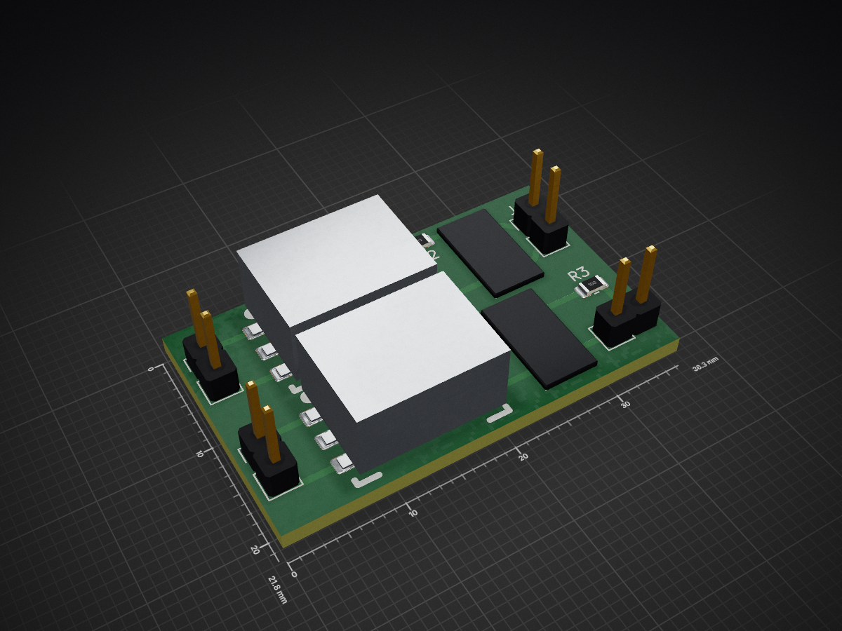
Ic-705 audio interface is an open-source printed circuit board by project802, from the project802/ic-705_audio_interface repository on GitHub. It is a 2-layer board of 36.3 × 21.8 mm with 11 parts on 16 nets, routed with 31 tracks and 0 vias.
It is built around the SM-LP-5001. Its parts include 4 resistors and 4 connectors. It belongs with the radio and wireless and audio and music boards of this library.
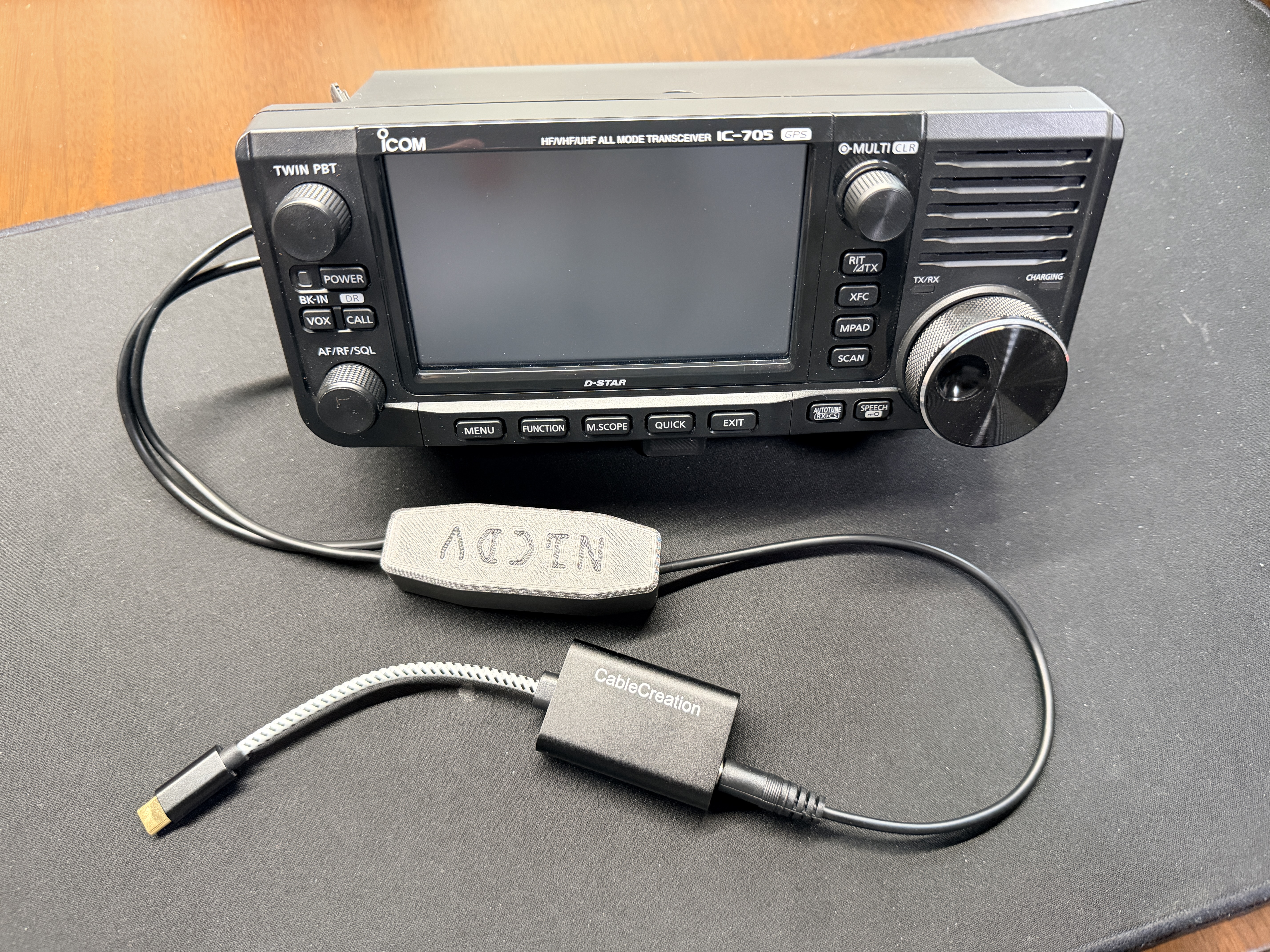
This project was done as a learning exercise for me, and a way to have some fun. I wanted to use my IC-705 with just an iPhone to drive digital mode communications, but limitations of both the radio and the phone meant things like straight USB or Bluetooth wouldn't work. There is a solution path with WiFi-based software or a Digirig, but I didn't want to be locked into a single app (even though I use it on my iPad and find it very good) or buy hardware when I thought I could make something myself and learn.
The result is a minimal solution that is ideal for remote or portable operation (such as POTA or SOTA) with iOS.
All said and done, I have got this working with iFTx and Greyline FT8 to successfully complete QSOs!
In the end, this device is just an audio level shifter with isolation. It can be used with any device (PC, tablet, phone) that has an analog audio input (microphone or line in) and an analog audio output. Just tune the trim pots to hit the voltage levels you need.
Have a PC? Just use the built-in USB functionality or Wi-Fi interface. This adds no value, whatsoever, over those options. This is really for phones using inexpensive (or free) apps that require VOX activation.
The radio presents a BT/USB interface to the iOS device, but there are two issues that prevent this from working:
There are also reports that the IC-705 has poor RFI rejection via USB so depending on what is plugged in, this could make digital mode operation difficult.
You can theoretically make these interfaces work if you manually activate PTT. That doesn't sound fun.
This is a valid solution. Cost is approximately $45 for a Digirig Lite and I'd estimate $20 (if you can buy individual parts) to make an adapter cable for the IC-705. I still can't confirm if the output levels to the radio are proper, but at least one person has said it functionally works.
https://forum.digirig.net/t/cable-for-icom-ic-705-and-mobile-ft8/10725
The app SDR-Control does work, but it is sold separately for iPhone and iPad. You would be nearly $100 into software to run on both devices. Its the best solution, objectively, but is costly and locks you into an app. If you change the radio, the app is useless. I happen to like how it works on my iPad, but I've seen some impressive work from other developers in the $2 to $4 range.
The basis for the design is an example circuit that Icom provides in their advanced manual. Addition of a capacitor on the MIC line is required to create a high resistance path to not activate PTT (the IC-705 uses the same pin for both MIC input and PTT).
Design files (PCB, schematic) can be found in the KiCad directory.
A screenshot of the schematic is also available for quick reference.
Icom doesn't seem to publish the MIC input electrical specifications. Through empirical testing, it seems the maximum IC-705 MIC input level before clipping is 50 mVpp.
The methodology was:
I landed on AF GAIN = 30 as that seems to be the highest value before output clipping occurs.
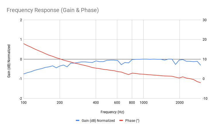
Below is the response of the audio interface when stimulated with a signal at the device output and captured at the radio mic input. It is very linear and only drops around 0.5 dB @ 200 Hz, which fits the FT8/4 use case very well. The radio filter(s) will attenuate much more aggressively in the lower sections of the sideband, so look out for loss of power.
This is a straight forward board to assemble. The IC-705 side uses a 3.5mm TRS for the speaker connector and a 2.5mm TRRS for the mic connector. I used a 3.5mm TRRS to connect to the phone side with the jumper soldered, but you can use two cables instead.
For PCB assembly, I recommend doing the SMT parts first, then the trim pots, then the cables.
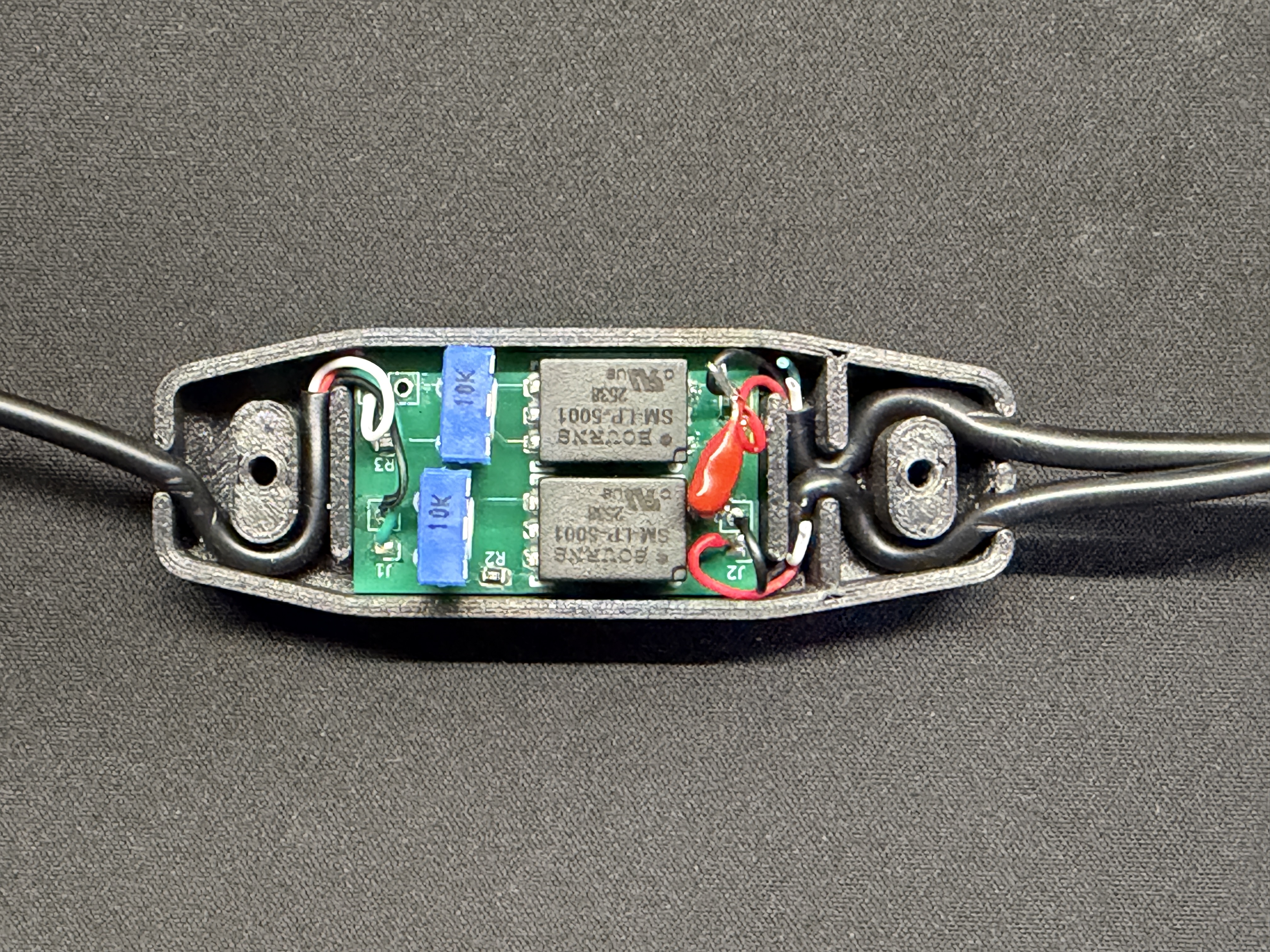
The output capacitor that goes inline with the IC-705 mic input was left off the PCB to keep the footprint as small as possible. Put one leg into the PCB and the other towards the cable.
DigiKey BOM @ $7
2.5mm TRRS cable @ $9 ($1.50/ea)
3.5mm TRRS cable @ $8 ($2/ea)
3.5mm TRS cable @ $8 ($4/ea)
USB audio interface (others will work, too)
Below is an image of the cable routing and capacitor placement. It is done this way for strain relief.
After assembly, tune the trim pots so that the MIC input for the IC-705 reaches 50 mVpp while calling CQ.
I set the device side mic to 45 mVpp as this was saturation for my device. To tune it yourself, use the record function to save a CQ TX to the microSD card, then play it back with AF GAIN = 30. You should get full scale output without clipping and use that to tune the trim pot. Pair with any free app or built-in program that shows the mic level input on your device.
At the time of writing, the total component cost was $14.50 and the PCB was $1.20/ea. I have 8 extra PCBs so create an issue here to contact me about getting one. Send me a self-addressed stamped envelope and I'll send you one for free.
IC-705:
iOS:
iFTx:
Greyline FT8
| Qty | Value | Footprint | References |
|---|---|---|---|
| 4 | Conn_01x02 | Connector_PinHeader_2.54mm:PinHeader_1x02_P2.54mm_Vertical | J1, J2, J3, J4 |
| 2 | 10k | Resistor_SMD:R_0805_2012Metric | R2, R3 |
| 2 | SM-LP-5001 | Project Footprints:SM-LP-5001 | T1, T2 |
| 2 | ~ | Project Footprints:H2.5 | R1, R4 |
| 1 | SolderJumper_2_Open | Jumper:SolderJumper-2_P1.3mm_Open_RoundedPad1.0x1.5mm | JP1 |
It measures 36.3 × 21.8 mm and has 2 copper layers, 1.6 mm thick.
11 parts, built around the SM-LP-5001. The full list of its parts is on this page, with links to each part's symbol and footprint where PCBKit's library has them.
From the project802/ic-705_audio_interface repository on GitHub, at the commit this page was made from: the board is KiCad/IC-705 Audio Interface.kicad_pcb and its schematic KiCad/IC-705 Audio Interface.kicad_sch. PCBKit opens the board in the browser, with nothing to install.
Its repository states no licence, so its author keeps all rights: ask project802 before reusing the design.


brucemack/microlink
An open source EchoLink/AllStarLink implementation that runs on a simple microcontroller.

google/mozc-devices
Circuit diagrams and firmware source code for Gboard DIY keyboards


FrameworkComputer/ExpansionCards
Reference designs and documentation to create Expansion Cards for the Framework Laptop

hoglet67/RGBtoHDMI
Bare-metal Raspberry Pi project that provides pixel-perfect sampling of Retro Computer RGB/YUV video and conversion to HDMI

hackclub/OnBoard
💡 Join 1,000 teenagers and make your first PCB with a $100 grant!