
2 layers98.9 × 48.3 mm

A Pretty Good Preamplifier for Stereo and Subwoofer Use
Preamp is an open-source printed circuit board by profdc9, from the profdc9/PrettyGoodPreamplifier repository on GitHub. It is a 2-layer board of 300 × 90 mm with 222 parts on 155 nets, routed with 2,108 tracks and 140 vias.
It is built around the LM4562NA, INA134UA and LM317, with the 1N4742A, 1N4747A and TIP42C among its other parts. Its parts include 72 capacitors, 53 resistors, 28 connectors, 18 diodes and 11 ICs. It belongs with the audio and music boards of this library.


This is a stereo preamplifier circuit designed by Daniel Marks, including schematic and gerbers.
It has the following features:
It is a two-sided PCB that can be manufactured cheaply by, for example, JLCPCB or PCBWay. The LM4562 is preferentially used for the op-amps, but NE5532 works fine too. The XLR input uses a THAT1206 or INA137 integrated circuit. The XLR output uses a THAT1646 or DRV134 integrated circuit.
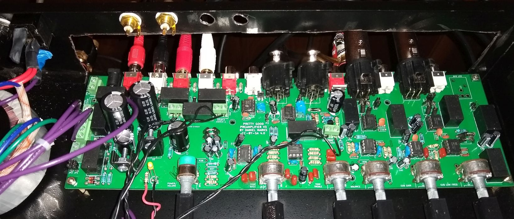
Here is a picture of the PCB
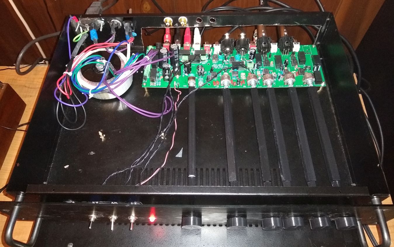
Here is a picture of the full preamplifier with the potentiometer extenders in the CAD directory:
| Qty | Value | Footprint | References |
|---|---|---|---|
| 21 | 100 nF | Capacitors_THT:C_Disc_D5.0mm_W2.5mm_P5.00mm | C10, C19, C20, C26, C27, C28, C30, C34, C37, C40, C41, C42, C43, C44, C45, C46 +5 |
| 18 | 47 uF | Capacitors_THT:CP_Radial_D5.0mm_P2.50mm | C6, C18, C21, C35, C36, C49, C50, C52, C53, C60, C61, C62, C66, C67, C68, C69 +2 |
| 16 | 10k | Resistors_THT:R_Axial_DIN0207_L6.3mm_D2.5mm_P7.62mm_Horizontal | R13, R14, R15, R16, R17, R18, R22, R24, R25, R26, R27, R28, R35, R36, R41, R46 |
| 14 | 1N4007 | Diodes_THT:D_DO-41_SOD81_P7.62mm_Horizontal | D2, D3, D5, D6, D7, D8, D9, D10, D11, D13, D14, D15, D16, D18 |
| 12 | DPDTRelay | Preamp:G2VRelay | RLY1, RLY2, RLY3, RLY4, RLY5, RLY6, RLY7, RLY8, RLY9, RLY10, RLY11, RLY12 |
| 9 | RCAJack | Preamp:RCAConnectorCommon | J4, J5, J10, J14, J15, J18, J19, J20, J21 |
| 8 | Conn_01x01 | Connectors:1pin | J6, J7, J8, J9, J25, J26, J27, J28 |
| 8 | FB | Inductors_THT:L_Axial_L7.0mm_D3.3mm_P10.16mm_Horizontal_Fastron_MICC | L1, L2, L3, L4, L5, L6, L7, L8 |
| 7 | 22 pF | Capacitors_THT:C_Disc_D5.0mm_W2.5mm_P5.00mm | C8, C11, C24, C25, C38, C39, C72 |
| 7 | 33 nF | Capacitors_THT:C_Disc_D5.0mm_W2.5mm_P5.00mm | C12, C13, C14, C15, C31, C32, C33 |
| 7 | PH | Pin_Headers:Pin_Header_Straight_1x02_Pitch2.54mm | JP3, JP4, JP5, JP6, JP7, JP8, JP9 |
| 6 | 10R | Resistors_THT:R_Axial_DIN0207_L6.3mm_D2.5mm_P7.62mm_Horizontal | R47, R49, R50, R51, R53, R54 |
| 5 | 100 pF | Capacitors_THT:C_Disc_D5.0mm_W2.5mm_P5.00mm | C29, C54, C55, C56, C57 |
| 5 | B100Kdual | Preamp:Dual_Potentiometer_Switch_WirePads | RV2, RV3, RV4, RV5, RV6 |
| 4 | 22k | Resistors_THT:R_Axial_DIN0207_L6.3mm_D2.5mm_P7.62mm_Horizontal | R8, R9, R10, R11 |
| 4 | 3300 pF | Capacitors_THT:C_Disc_D5.0mm_W2.5mm_P5.00mm | C16, C17, C22, C23 |
| 4 | 47k | Resistors_THT:R_Axial_DIN0207_L6.3mm_D2.5mm_P7.62mm_Horizontal | R21, R31, R33, R34 |
| 4 | 4k7 | Resistors_THT:R_Axial_DIN0207_L6.3mm_D2.5mm_P7.62mm_Horizontal | R2, R3, R4, R7 |
| 4 | Conn_01x02 | Connectors_Terminal_Blocks:TerminalBlock_bornier-2_P5.08mm | J2, J3, J23, J24 |
| 4 | LM4562 | Housings_DIP:DIP-8_W7.62mm_Socket | U3, U4, U5, U6 |
| 4 | NC | Resistors_THT:R_Axial_DIN0207_L6.3mm_D2.5mm_P7.62mm_Horizontal | R37, R38, R39, R40 |
| 3 | 100R | Resistors_THT:R_Axial_DIN0207_L6.3mm_D2.5mm_P7.62mm_Horizontal | R29, R30, R32 |
| 3 | 100k | Resistors_THT:R_Axial_DIN0207_L6.3mm_D2.5mm_P7.62mm_Horizontal | R42, R45, R48 |
| 3 | 3k3 | Resistors_THT:R_Axial_DIN0207_L6.3mm_D2.5mm_P7.62mm_Horizontal | R19, R20, R23 |
| 3 | SW_SPST | Connectors_Terminal_Blocks:TerminalBlock_bornier-2_P5.08mm | SW1, SW2, SW3 |
| 3 | THAT1646 | Housings_DIP:DIP-8_W7.62mm_Socket | U7, U8, U9 |
| 3 | XLR4BODYPIN | Preamp:IOXLR3MEH | J11, J12, J13 |
| 2 | 1500 uF | Capacitors_THT:CP_Radial_D10.0mm_P5.00mm | C1, C2 |
| 2 | 1N4742A | Diodes_THT:D_DO-41_SOD81_P7.62mm_Horizontal | D1, D4 |
| 2 | 1R | Resistors_THT:R_Axial_DIN0309_L9.0mm_D3.2mm_P12.70mm_Horizontal | R43, R44 |
| 2 | 220 uF | Capacitors_THT:CP_Radial_D7.5mm_P2.50mm | C47, C48 |
| 2 | 2200 uF | Capacitors_THT:CP_Radial_D12.5mm_P5.00mm | C4, C5 |
| 2 | 470 pF | Capacitors_THT:C_Disc_D5.0mm_W2.5mm_P5.00mm | C3, C7 |
| 2 | 560R | Resistors_THT:R_Axial_DIN0207_L6.3mm_D2.5mm_P7.62mm_Horizontal | R5, R6 |
| 2 | INA134 | Pin_Headers:Pin_Header_Straight_1x02_Pitch2.54mm | JP1, JP2 |
| 2 | THAT1200 | Housings_DIP:DIP-8_W7.62mm_Socket | U10, U11 |
| 2 | XLR4BODYPIN | Preamp:IOXLR3FEH | J16, J17 |
| 1 | 1000 uF | Capacitors_THT:CP_Radial_D7.5mm_P2.50mm | C65 |
| 1 | 150R | Resistors_THT:R_Axial_DIN0309_L9.0mm_D3.2mm_P12.70mm_Horizontal | R1 |
| 1 | 1N4747A | Diodes_THT:D_DO-41_SOD81_P7.62mm_Horizontal | D17 |
| 1 | 2N3904 | TO_SOT_Packages_THT:TO-92_Inline_Wide | Q1 |
| 1 | 2k2 | Resistors_THT:R_Axial_DIN0207_L6.3mm_D2.5mm_P7.62mm_Horizontal | R12 |
| 1 | 470 uF | Capacitors_THT:CP_Radial_D10.0mm_P5.00mm | C64 |
| 1 | A10Kdual | Preamp:Dual_Potentiometer_Switch_Wide_WirePads | RV1 |
| 1 | Conn_01x03 | Connectors_Terminal_Blocks:TerminalBlock_bornier-3_P5.08mm | J1 |
| 1 | Jack-DC | Connectors:BARREL_JACK | J22 |
| 1 | LED | LEDs:LED_D5.0mm | D12 |
| 1 | LM317 | TO_SOT_Packages_THT:TO-220-3_Vertical | U1 |
| 1 | LM337 | TO_SOT_Packages_THT:TO-220-3_Vertical | U2 |
| 1 | TIP42C | TO_SOT_Packages_THT:TO-220-3_Vertical | Q2 |
It measures 300 × 90 mm and has 2 copper layers, 1.6 mm thick.
222 parts, built around the LM4562NA, INA134UA, LM317 and 1N4742A. The full list of its parts is on this page, with links to each part's symbol and footprint where PCBKit's library has them.
From the profdc9/PrettyGoodPreamplifier repository on GitHub, at the commit this page was made from: the board is Preamp.kicad_pcb. PCBKit opens the board in the browser, with nothing to install.
Its repository states no licence, so its author keeps all rights: ask profdc9 before reusing the design.


alvaroalea/all-spectrum-clones
Schematic of a 8bit computer, clone of Sinclair ZX Spectrum


meldddiiiii/aspen-langmuir-pcb
KiCad redesign of the USC ASPEN single Langmuir probe sweep board, for the Fall 2026 ASPEN PCB competition.

Operationorange01/Flyback-Driver
driver for high voltage flyback transformer


bquangDinh/diy-esp32-thermostat
Design custom thermostat with ESP32, using 24VAC, battery management for backup, USB, etc