

4 layers157.5 × 98 mm
BeamBender BigBox
kavanoz64/BeamBender-BigBox
An AGA digital scandoubler and HDMI output card for the Amiga 4000, with Amiga 2000 / 3000 support.
221 parts12
 proboterror/RGB_SCART_VGA_Breakout
RGB SCART / VGA breakout board
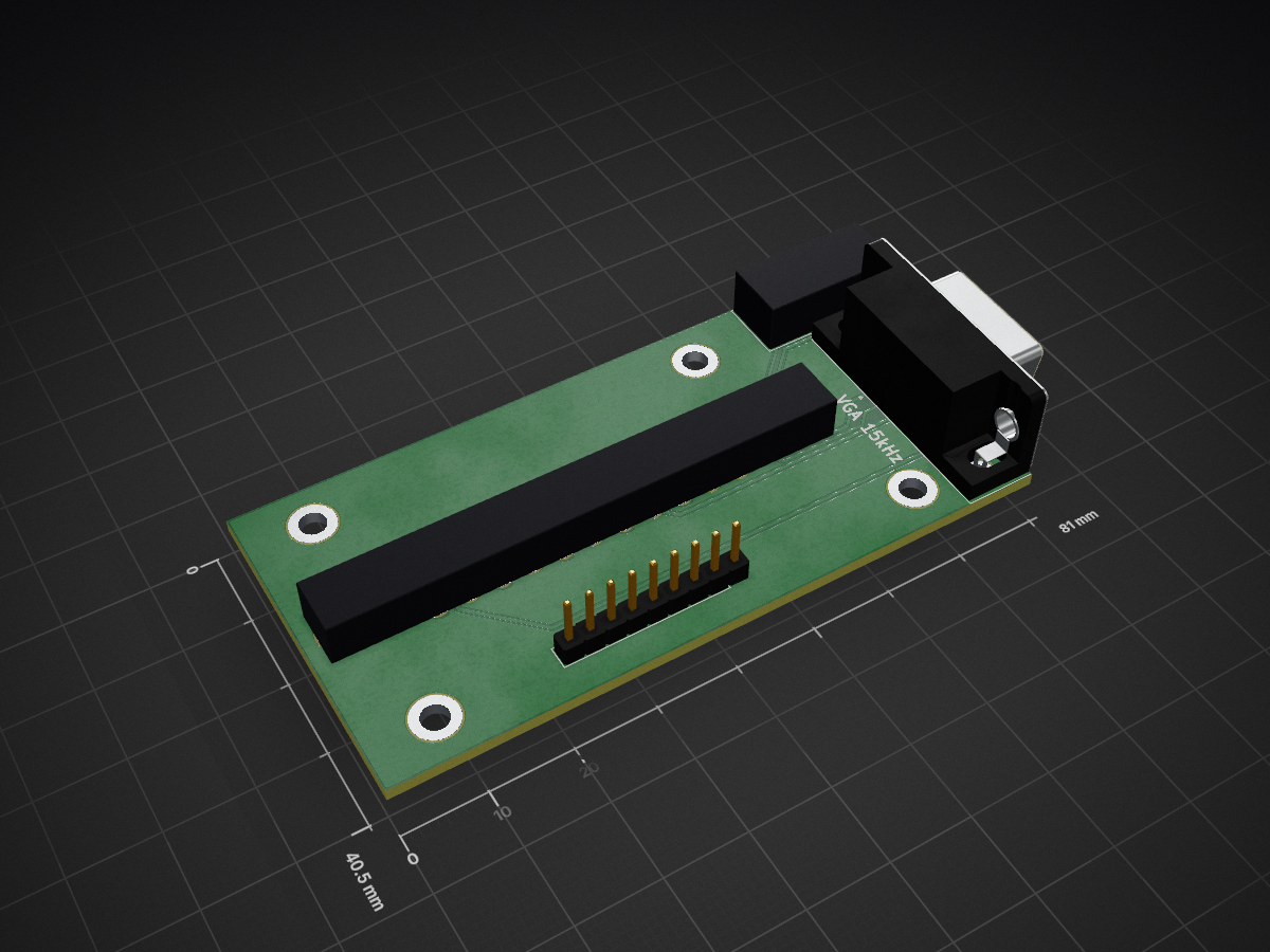
RGB SCART VGA Breakout is an open-source printed circuit board by proboterror, from the proboterror/RGB_SCART_VGA_Breakout repository on GitHub. It is a 2-layer board of 81 × 40.5 mm with 25 parts on 31 nets, routed with 105 tracks and 0 vias.
It is built around the BAT54W and SJ1-3535NG. Its parts include 10 resistors, 8 connectors, 4 capacitors and 2 diodes. It belongs with the lEDs and displays and interfaces and adapters boards of this library.
For RGB/SCART modding JVC, SONY PVM video monitors and consumer CRT TVs.
Mounting holes step 10 mm, matching JVC monitors case.
Continuation of RGB SCART Breakout board.
Features:
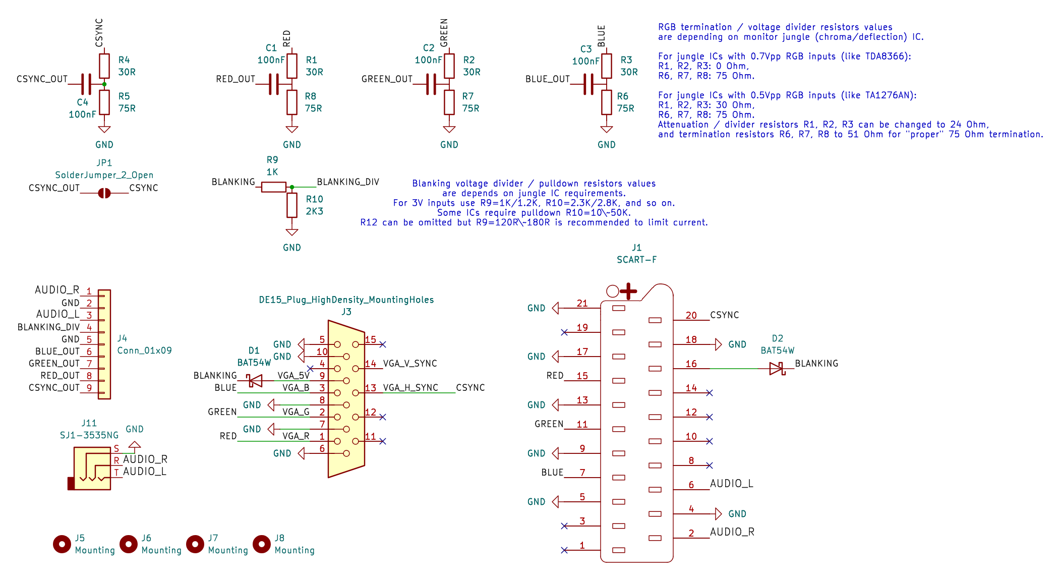
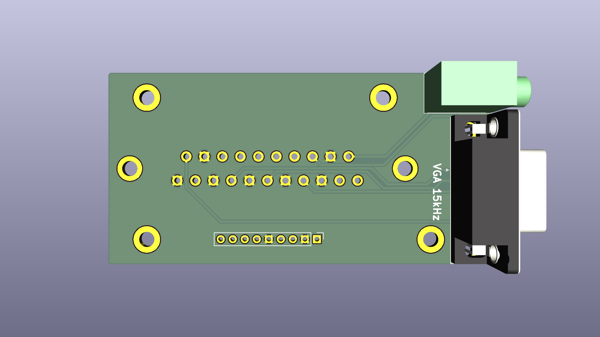
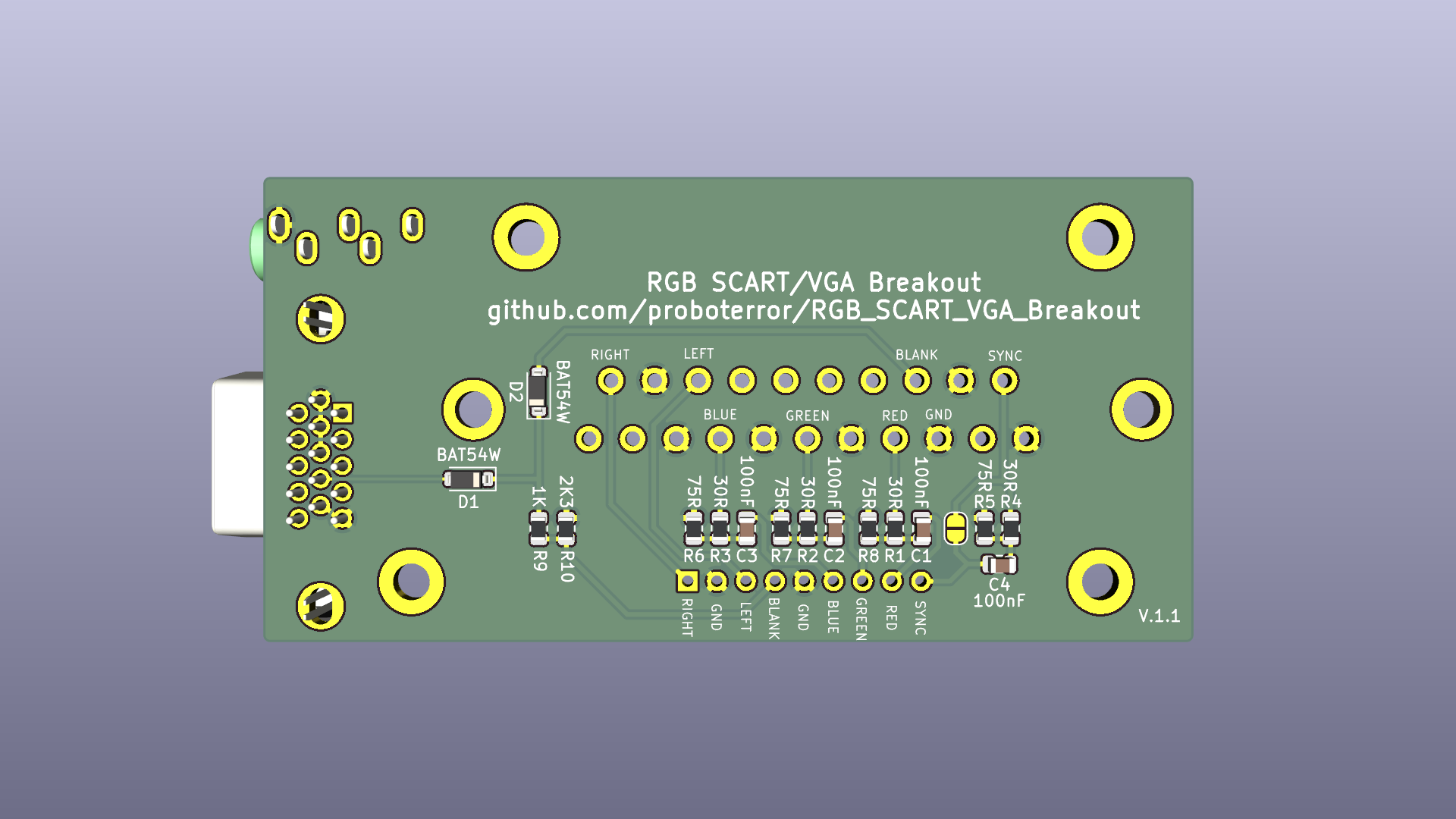
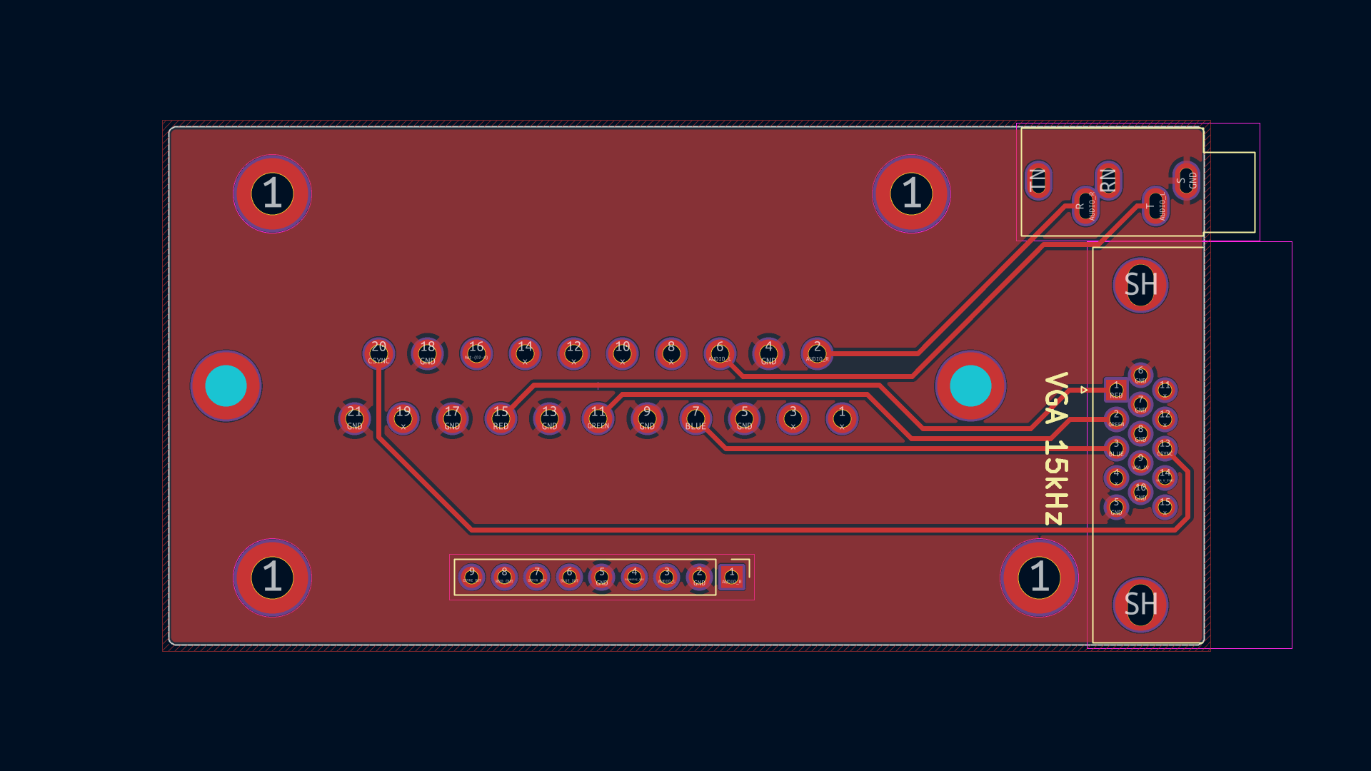
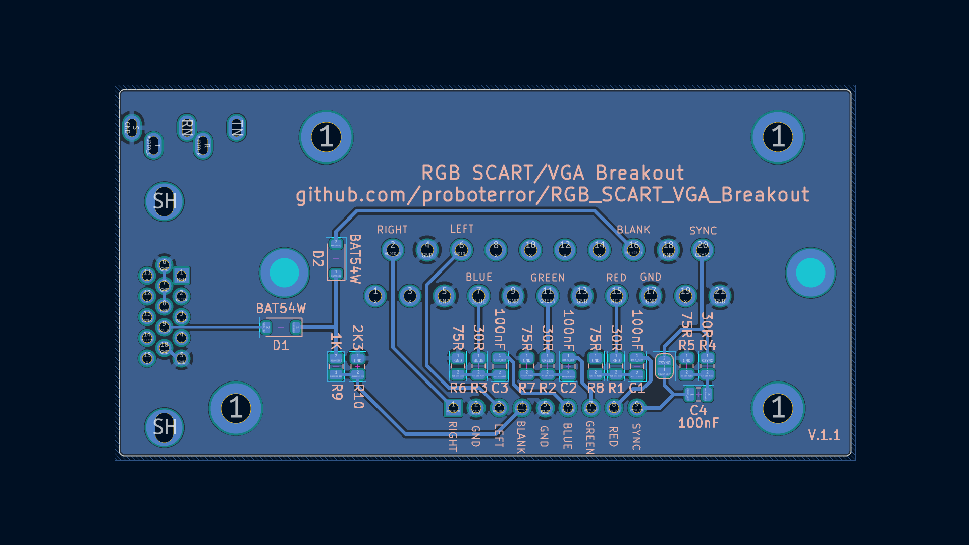
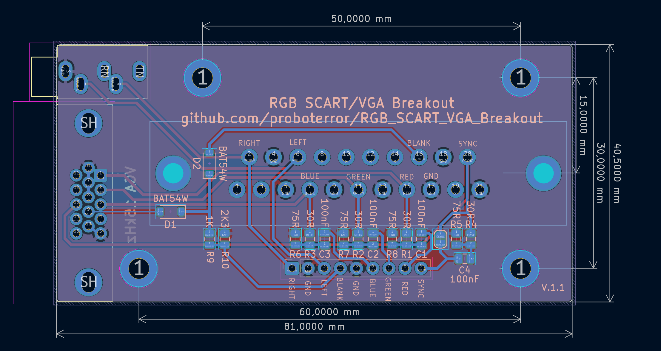
| Reference | Value | Footprint | Qty |
|---|---|---|---|
| C1,C2,C3,C4 | 100nF | 0805 | 4 |
| D1,D2 | BAT54W | Diode_SMD:D_SOD-123 | 2 |
| J1 | SCART-F | CS-102 (SCART-21S) | 1 |
| J3 | DE15 Socket / DSUB-15-HD / VGA | DSUB-15-HD_Socket_Horizontal P2.29x1.90mm EdgePinOffset3.03mm MountingHolesOffset4.94mm | 1 |
| J11 | SJ1-3535NG | CUI/Same Sky Device SJ1-3535NG | 1 |
| R1,R2,R3,R4 | 0R/24R/30R | 0805 | 4 |
| R5,R6,R7,R8 | 75R/51R | 0805 | 4 |
| R9 | 1K/1K2/4K7 | 0805 | 1 |
| R10 | 2.3K/2K8/10K | 0805 | 1 |
Notes:
| Qty | Value | Footprint | References |
|---|---|---|---|
| 4 | 100nF | Capacitor_SMD:C_0805_2012Metric | C1, C2, C3, C4 |
| 4 | 30R | Resistor_SMD:R_0805_2012Metric | R1, R2, R3, R4 |
| 4 | 75R | Resistor_SMD:R_0805_2012Metric | R5, R6, R7, R8 |
| 4 | Mounting | MountingHole:MountingHole_3.2mm_M3_DIN965_Pad | J5, J6, J7, J8 |
| 2 | BAT54W | Diode_SMD:D_SOD-123 | D1, D2 |
| 1 | 1K | Resistor_SMD:R_0805_2012Metric | R9 |
| 1 | 2K3 | Resistor_SMD:R_0805_2012Metric | R10 |
| 1 | Conn_01x09 | Connector_PinHeader_2.54mm:PinHeader_1x09_P2.54mm_Vertical | J4 |
| 1 | DE15_Plug_HighDensity_MountingHoles | Connector_Dsub:DSUB-15-HD_Socket_Horizontal_P2.29x1.90mm_EdgePinOffset3.03mm_Housed_MountingHolesOffset4.94mm | J3 |
| 1 | SCART-F | k-scartx-024:K-SCARTX-024 | J1 |
| 1 | SJ1-3535NG | Connector_Audio:Jack_3.5mm_CUI_SJ1-3535NG_Horizontal | J11 |
| 1 | SolderJumper_2_Open | Jumper:SolderJumper-2_P1.3mm_Open_RoundedPad1.0x1.5mm | JP1 |
kavanoz64/BeamBender-BigBox
An AGA digital scandoubler and HDMI output card for the Amiga 4000, with Amiga 2000 / 3000 support.


frindaddy/digichiver
Archival hardware/firmware for the MM54104 Digitalker chip

polpo/picogus
Emulation of ISA sound cards and CD-ROM on Raspberry Pi Pico (GUS, SB/Adlib, MPU-401, Tandy, CMS, Panasonic CD-ROM) with USB mouse/joystick support

demik/oldworld
Development ressources for Old World Macintosh (68k and NuBus PPC) and a few related things…

alberto-grl/H7RTX-V2-Schematics-PCB
Schematics and PCB for a three-band direct sampling SDR. Using the internal ADC of an MCU, TX power is about 5 W. USB powered. Firmware code: https://github.com/alberto-grl/750RTX

It measures 81 × 40.5 mm and has 2 copper layers, 1.6 mm thick.
25 parts, built around the BAT54W and SJ1-3535NG. The full list of its parts is on this page, with links to each part's symbol and footprint where PCBKit's library has them.
From the proboterror/RGB_SCART_VGA_Breakout repository on GitHub, at the commit this page was made from: the board is KiCad/RGB_SCART_VGA_Breakout.kicad_pcb and its schematic KiCad/RGB_SCART_VGA_Breakout.kicad_sch. PCBKit opens the board in the browser, with nothing to install.
Its repository states no licence, so its author keeps all rights: ask proboterror before reusing the design.