2 layers34.3 × 99.7 mm
Truss connector breakout
practable/truss
The truss remote laboratory has been designed for use with Structural Engineering and Engineering Design courses at the University of Edinburgh.
14 partsAGPL-3.0

 practable/truss
The truss remote laboratory has been designed for use with Structural Engineering and Engineering Design courses at the University of Edinburgh.
Truss PCB is an open-source printed circuit board by practable, from the practable/truss repository on GitHub, published under the AGPL-3.0 licence. It is a 2-layer board of 114.3 × 102.9 mm with 208 parts on 167 nets, routed with 1,952 tracks and 282 vias.
It is built around the HX711, LM2596S-ADJ and TXS0108EPW, with the AMS1117-3.3, AMS1117-5.0 and BC807 among its other parts. Its parts include 51 resistors, 27 capacitors, 22 connectors, 13 ICs and 11 diodes. It belongs with the AVR (ATmega, ATtiny) boards of this library.


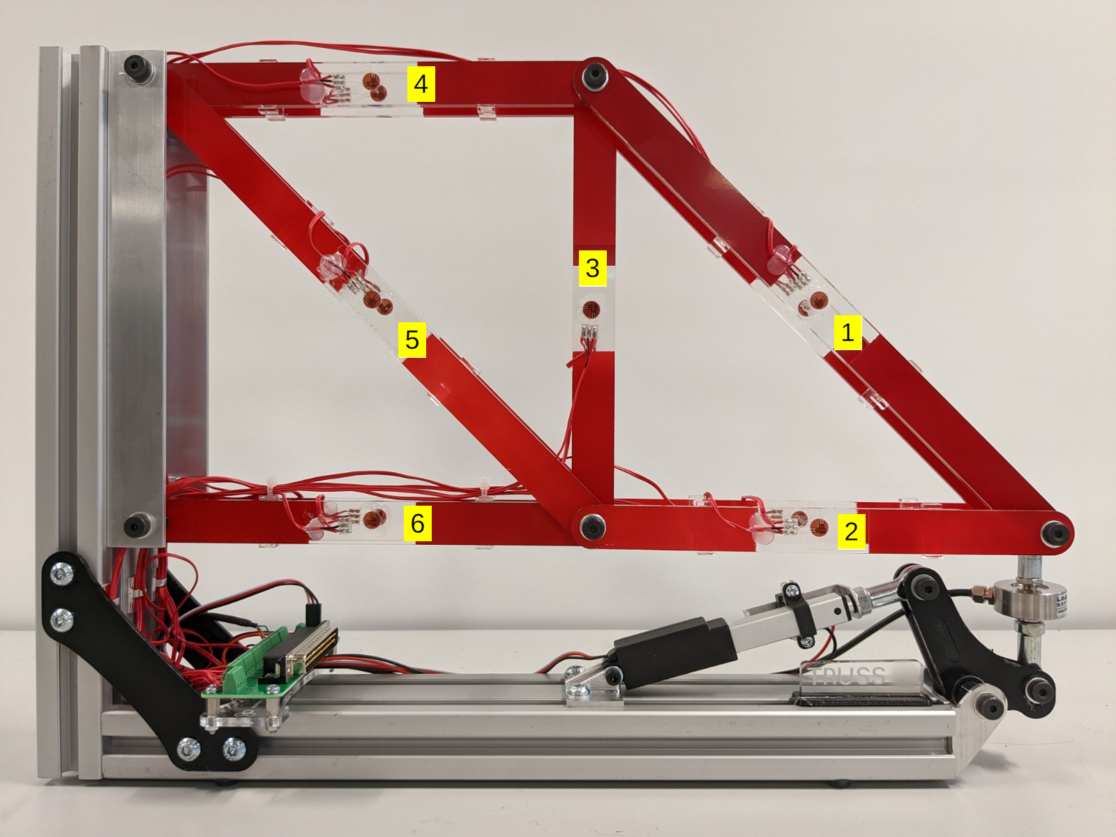
The truss remote laboratory has been designed for use with Structural Engineering and Engineering Design courses at the University of Edinburgh. The truss consists of 6 members, each with a full-bridge strain gauge arrangement using two biaxial strain gauges (Kyowa KFGS-2-120-D16-11). Strain gauge voltages are converted to digital signals using the HX711 ADC and this HX711 library is used to read and tare the gauges. The truss is loaded using a linear servo.
User Interfaces have been designed with Vue3.js and built with Vite. There are currently three distinct versions of the UI that are built for production:
See here for details of the differences.
The differences in the above UI versions amount to very simple changes in the Vue files.
The load force can be controlled with either a slider or simple buttons (as well experimental versions of a skeuomorphic display and gamepad control). Simply update the loadControlVersion parameter in App.vue.
loadControlVersion: 1, //0 => input field, 1=> slider, 2=>simulation of physical knob, 3 => direct commands typed, 4 => GamePad, 5 => open day, simple buttonsTo change whether the load force is displayed or the theoretical strains are available, update the boolean parameters in src/modules/uiStore.js:
show_force: false,       //should force values be displayed on the UI
show_theory: false, //should the theoretical values component be available on the UIThe truss remote lab has been designed around the Arduino Nano 33 IoT. The firmware uses a state machine with 11 states, including reading, writing, taring and resetting strain gauges and moving the linear actuator. A single microcontroller performs both reading and writing of data. The state machine will remain in the READ state until a user command to change state. Upon performing that state the state machine will return to READ. The required libraries are included here.
The firmware sends and receives JSON messages, eg:
Mode control, received from UI through Serial (for all commands see SerialCommands:
{"set": "position", "to": value}
{"set": "mode", "to": "move"}
{"set": "mode", "to":"tare_all"}
Sending data to UI through Serial:
{"load_cell":"20.0", "gauge_1": "100.0", "gauge_2": "100.0", "gauge_3": "100.0", "gauge_4": "100.0", "gauge_5": "100.0", "gauge_6": "100.0", "state":"1", "pos":"10"}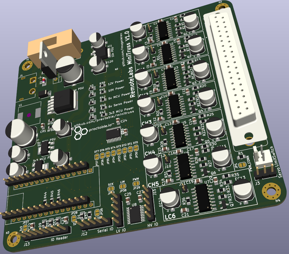
The PCB requires a 12V input and provides output voltages for different components: 10V (load cell excitation voltage), 6V (linear actuator power) and 5V (strain gauge excitation voltage). Details of jumper requirements for setting up the PCB in different modes will be added (TODO).
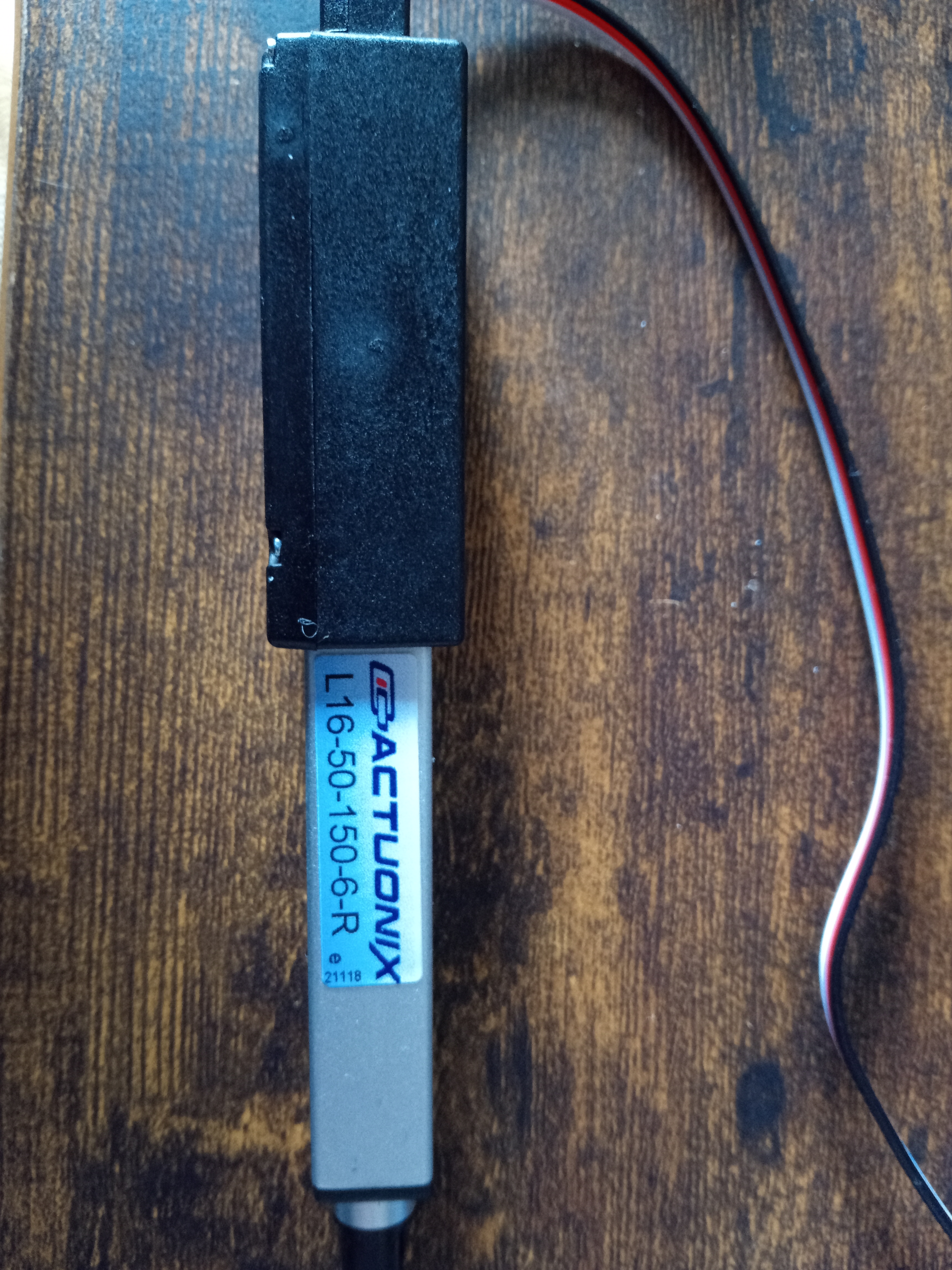
The Actuonix L16 linear actuator uses the custom library LinearServo for setting its position. It has a 50mm stroke length, but is limited in this remote lab to a maximum of 20% extension (providing around 150N of load on the truss).
If a strain gauge value no longer reads an acceptable result (within your experimental tolerance) then the scale factor needs to be updated in the firmware.
Using the debug UI (or any other means of sending a JSON command through Websocket to the experiment): send the new calibration data:
{"set":"cal","to":[2.0,2.1,2.2,2.3,2.4,2.5,2.6],"auth":"foo"}Using the auth code that you set up initially.
Then reset to the STARTUP state so that the firmware loads the new calibration data:
{"set":"state","to":"STATE_STARTUP"}| Qty | Value | Footprint | References |
|---|---|---|---|
| 27 | 100n | Capacitor_SMD:C_0805_2012Metric_Pad1.18x1.45mm_HandSolder | C1, C2, C10, C11, C12, C13, C14, C15, C16, C17, C18, C19, C20, C21, C22, C23 +11 |
| 17 | 10u | Capacitor_SMD:CP_Elec_6.3x5.9 | EC1, EC2, EC3, EC4, EC5, EC6, EC7, EC8, EC10, EC11, EC12, EC13, EC14, EC20, EC21, EC22 +1 |
| 14 | 100r | Resistor_SMD:R_0805_2012Metric_Pad1.20x1.40mm_HandSolder | R4, R5, R9, R10, R14, R15, R19, R20, R24, R25, R29, R30, R34, R35 |
| 14 | 10k | Resistor_SMD:R_0805_2012Metric_Pad1.20x1.40mm_HandSolder | R1, R6, R11, R16, R21, R26, R31, R36, R40, R47, R48, R49, R50, R51 |
| 7 | 12k | Resistor_SMD:R_0805_2012Metric_Pad1.20x1.40mm_HandSolder | R2, R7, R12, R17, R22, R27, R32 |
| 7 | 33k | Resistor_SMD:R_0805_2012Metric_Pad1.20x1.40mm_HandSolder | R3, R8, R13, R18, R23, R28, R33 |
| 7 | BC807 | Package_TO_SOT_SMD:SOT-23 | Q1, Q2, Q3, Q4, Q5, Q6, Q7 |
| 7 | Gain | Jumper:SolderJumper-2_P1.3mm_Bridged_RoundedPad1.0x1.5mm | JP2, JP5, JP8, JP11, JP14, JP17, JP21 |
| 7 | HX711 | Package_SO:SOP-16_4.55x10.3mm_P1.27mm | U1, U2, U3, U4, U5, U6, U7 |
| 7 | INB GND | Jumper:SolderJumper-3_P1.3mm_Bridged12_RoundedPad1.0x1.5mm_DoubleJoined_SMALL | JP3, JP6, JP9, JP12, JP15, JP18, JP24 |
| 7 | IN_B | Connector_PinHeader_1.27mm:PinHeader_1x02_P1.27mm_Vertical | J5, J6, J7, J8, J9, J10, J11 |
| 6 | Sample Rate | Jumper:SolderJumper-2_P1.3mm_Bridged_RoundedPad1.0x1.5mm | JP4, JP7, JP10, JP13, JP16, JP19 |
| 5 | 1k | Resistor_SMD:R_0805_2012Metric_Pad1.20x1.40mm_HandSolder | R37, R43, R44, R45, R46 |
| 4 | LED | Diode_SMD:D_0805_2012Metric_Pad1.15x1.40mm_HandSolder | D1, D9, D10, D11 |
| 4 | MountingHole_M3 | MountingHole:MountingHole_3.2mm_M3_Pad_Via | H1, H2, H3, H4 |
| 3 | 22u | Capacitor_SMD:CP_Elec_6.3x5.9 | EC17, EC18, EC19 |
| 2 | 330r | Resistor_SMD:R_0805_2012Metric_Pad1.20x1.40mm_HandSolder | R38, R39 |
| 2 | 8k2 | Resistor_SMD:R_0805_2012Metric_Pad1.20x1.40mm_HandSolder | R41, R42 |
| 2 | GND | Connector_PinHeader_2.54mm:PinHeader_1x03_P2.54mm_Vertical | J16, J17 |
| 2 | TXS0108EPW | Package_SO:TSSOP-20_4.4x6.5mm_P0.65mm | U8, U9 |
| 2 | pwr_tie | NetTie:NetTie-8-15A_1oz_2oz | N2, N3 |
| 1 | 100u | Capacitor_SMD:CP_Elec_10x10 | EC15 |
| 1 | 10V | Connector_PinHeader_2.54mm:PinHeader_1x01_P2.54mm_Vertical | J22 |
| 1 | 10V Power | Diode_SMD:D_0805_2012Metric_Pad1.15x1.40mm_HandSolder | D6 |
| 1 | 12V | Connector_PinHeader_2.54mm:PinHeader_1x01_P2.54mm_Vertical | J18 |
| 1 | 12V Power | Diode_SMD:D_0805_2012Metric_Pad1.15x1.40mm_HandSolder | D8 |
| 1 | 1N5821 | Diode_SMD:D_SMA | D4 |
| 1 | 33uH | Inductor_SMD:L_12x12mm_H8mm | L1 |
| 1 | 3A | Fuse:Fuseholder_Cylinder-5x20mm_Stelvio-Kontek_PTF78_Horizontal_Open | F1 |
| 1 | 3V3 | Connector_PinHeader_2.54mm:PinHeader_1x01_P2.54mm_Vertical | J21 |
| 1 | 3k3 | Resistor_SMD:R_0805_2012Metric_Pad1.20x1.40mm_HandSolder | RFB2 |
| 1 | 3n3 | Capacitor_SMD:C_0805_2012Metric_Pad1.18x1.45mm_HandSolder | Cff1 |
| 1 | 3v3 | Jumper:SolderJumper-2_P1.3mm_Open_RoundedPad1.0x1.5mm | JP27 |
| 1 | 3v3 Power | Diode_SMD:D_0805_2012Metric_Pad1.15x1.40mm_HandSolder | D3 |
| 1 | 5V | Connector_PinHeader_2.54mm:PinHeader_1x01_P2.54mm_Vertical | J20 |
| 1 | 5v | Jumper:SolderJumper-2_P1.3mm_Open_RoundedPad1.0x1.5mm | JP28 |
| 1 | 5v Power | Diode_SMD:D_0805_2012Metric_Pad1.15x1.40mm_HandSolder | D7 |
| 1 | 680u | Capacitor_SMD:CP_Elec_10x10 | EC28 |
| 1 | 6V | Connector_PinHeader_2.54mm:PinHeader_1x01_P2.54mm_Vertical | J19 |
| 1 | 6v Power | Diode_SMD:D_0805_2012Metric_Pad1.15x1.40mm_HandSolder | D5 |
| 1 | 860r | Resistor_SMD:R_0805_2012Metric_Pad1.20x1.40mm_HandSolder | RFB1 |
| 1 | AMS1117-3.3 | Package_TO_SOT_SMD:SOT-223-3_TabPin2 | U13 |
| 1 | AMS1117-5.0 | Package_TO_SOT_SMD:SOT-223-3_TabPin2 | U12 |
| 1 | Arduino_Nano_v3.x | Module:Arduino_Nano | A1 |
| 1 | BAJ0BC0FP-E2 | Package_TO_SOT_SMD:TO-252-2 | IC1 |
| 1 | BZV55B9V1 | Diode_SMD:D_MiniMELF | D2 |
| 1 | Base | Jumper:SolderJumper-2_P1.3mm_Bridged_RoundedPad1.0x1.5mm | JP23 |
| 1 | DT0 | Jumper:SolderJumper-2_P1.3mm_Open_RoundedPad1.0x1.5mm | JP30 |
| 1 | DT1 | Jumper:SolderJumper-2_P1.3mm_Open_RoundedPad1.0x1.5mm | JP31 |
| 1 | DT2 | Jumper:SolderJumper-2_P1.3mm_Open_RoundedPad1.0x1.5mm | JP32 |
| 1 | DT3 | Jumper:SolderJumper-2_P1.3mm_Open_RoundedPad1.0x1.5mm | JP33 |
| 1 | DT4 | Jumper:SolderJumper-2_P1.3mm_Open_RoundedPad1.0x1.5mm | JP34 |
| 1 | DT5 | Jumper:SolderJumper-2_P1.3mm_Open_RoundedPad1.0x1.5mm | JP35 |
| 1 | DT6 | Jumper:SolderJumper-2_P1.3mm_Open_RoundedPad1.0x1.5mm | JP36 |
| 1 | DT7 | Jumper:SolderJumper-2_P1.3mm_Open_RoundedPad1.0x1.5mm | JP37 |
| 1 | HV IO | Connector_PinHeader_2.54mm:PinHeader_1x05_P2.54mm_Vertical | J15 |
| 1 | IO Header | Connector_PinHeader_2.54mm:PinHeader_1x08_P2.54mm_Vertical | J13 |
| 1 | IRF5305_PBF | Package_TO_SOT_THT:TO-220-3_Vertical | Q8 |
| 1 | LC Vsup | Jumper:SolderJumper-3_P1.3mm_Open_RoundedPad1.0x1.5mm_NumberLabels | JP20 |
| 1 | LIM | Jumper:SolderJumper-2_P1.3mm_Open_RoundedPad1.0x1.5mm | JP38 |
| 1 | LM2596S-ADJ | Package_TO_SOT_SMD:TO-263-5_TabPin3 | U11 |
| 1 | LOGO | 000_Graphics_Immo:Remote Labs SN Block | G*** |
| 1 | LOGO | 000_Graphics_Immo:practactable.io_text_80x30 | G*** |
| 1 | LOGO | 000_Graphics_Immo:practactable.io_text_20x8 | G*** |
| 1 | LV IO | Connector_PinHeader_2.54mm:PinHeader_1x05_P2.54mm_Vertical | J14 |
| 1 | LimitSwitch | Connector_Molex:Molex_KK-254_AE-6410-02A_1x02_P2.54mm_Vertical | J2 |
| 1 | PWM | Jumper:SolderJumper-2_P1.3mm_Open_RoundedPad1.0x1.5mm | JP29 |
| 1 | PWM_CONN | Jumper:SolderJumper-2_P1.3mm_Open_RoundedPad1.0x1.5mm | JP1 |
| 1 | SCK | Jumper:SolderJumper-2_P1.3mm_Open_RoundedPad1.0x1.5mm | JP39 |
| 1 | SampleRate | Jumper:SolderJumper-2_P1.3mm_Bridged_RoundedPad1.0x1.5mm | JP25 |
| 1 | Serial IO | Connector_PinHeader_2.54mm:PinHeader_1x05_P2.54mm_Vertical | J12 |
| 1 | Servo | Connector_PinHeader_2.54mm:PinHeader_1x03_P2.54mm_Vertical | J3 |
| 1 | Truss Connection | Connector_Dsub:DSUB-37_Female_Vertical_P2.77x2.84mm_MountingHoles | J4 |
| 1 | VFB | Jumper:SolderJumper-2_P1.3mm_Open_RoundedPad1.0x1.5mm | JP22 |
| 1 | V_USB | Jumper:SolderJumper-2_P1.3mm_Open_RoundedPad1.0x1.5mm | JP26 |
| 1 | XT60_60A_male | Connector_AMASS:AMASS_XT60PW-M | J1 |
It measures 114.3 × 102.9 mm and has 2 copper layers, 1.6 mm thick.
208 parts, built around the HX711, LM2596S-ADJ, TXS0108EPW and AMS1117-3.3. The full list of its parts is on this page, with links to each part's symbol and footprint where PCBKit's library has them.
From the practable/truss repository on GitHub, at the commit this page was made from: the board is mini-truss-pcb/truss_PCB/truss_PCB.kicad_pcb and its schematic mini-truss-pcb/truss_PCB-backups/TRUSS PCB VERSION 1/actuator_sch.kicad_sch. PCBKit opens the board in the browser, with nothing to install.
Its repository publishes it under the AGPL-3.0 licence: you may reuse it on that licence's terms (keep the author's notice, and for a copyleft licence share your changes alike).
practable/truss
The truss remote laboratory has been designed for use with Structural Engineering and Engineering Design courses at the University of Edinburgh.

practable/supervisor-pcb
Allow students to program a remote labs experiment themselves, while protecting hardware from damage due to misfunction

reivax-boucoi/PCB_Kicad
Repo for all my home projects involving PCBs developped with Kicad

getriscvyy/divesync-heavy
A syringe-actuated buoyancy control device developed at the Bio-Inspired Robotics and Controls Lab at University of Houston.

danielsimonreinhardt/microHIL
microHIL is a self-developed testing device for setting up a basic hardware-in-the-loop environment

Shubham-Khandelwal1/Universal-Robotic-Arm-Driver
The architecture follows a per-joint control philosophy, where each PCB operates as an independent node responsible for motor control and feedback acquisition, while communicating with a central compute unit (Jetson).

ThorbenMoos/Cloneless_artifacts
PCB designs, FPGA controllers, verification collateral and software artifacts related to the Cloneless series of tamper-resistant open-source ASICs

practable/iso-power-pcb
Remote power control board for ISO experiment containers, used for remote labs projects

joshcarter/tensile_test
Program and data for the testing of tensile strength of 3D printed parts