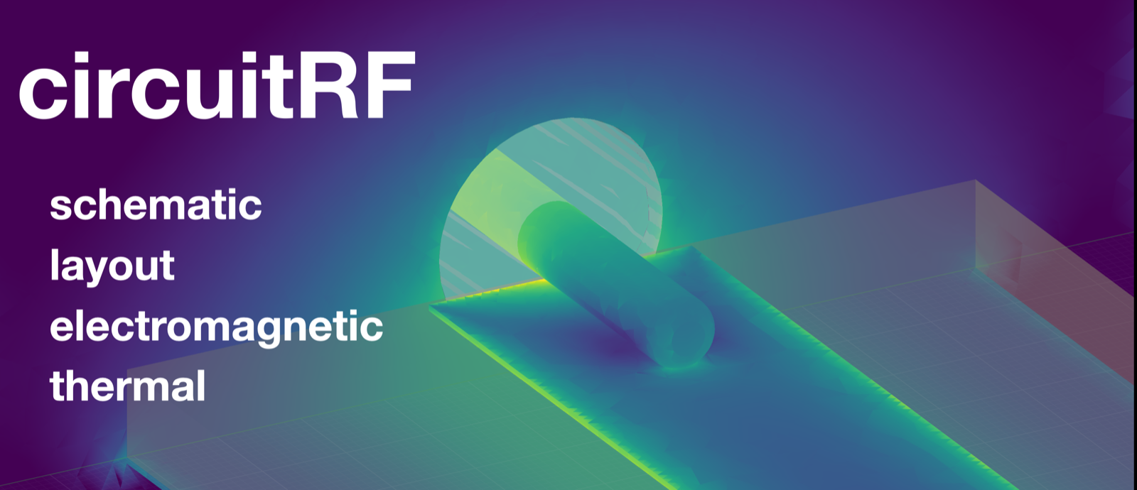
Full featured RF circuit + electromagnetic simulator. DC, S-parameters, harmonic balance, loadpull, envelope. Also supports 2D and 3D layout and design and electromagnetic MoM, FEM, FDTD + thermal FEM.
Two sided is an open-source printed circuit board by potatobeanradio, from the potatobeanradio/circuitRF repository on GitHub, published under the MIT licence. It is a 2-layer board with 9 parts on 4 nets.
Its parts include 3 resistors, 3 transistors, 2 connectors and 1 IC. It belongs with the radio and wireless and audio and music boards of this library.
README
README.md
EDA tool for RF design — for the RF community, by the RF community.
circuitRF is a full-featured EDA tool for RF and microwave design — schematic capture + nonlinear analysis, layout and
EM and thermal simulation in one cross-platform application. DC, S-parameter, harmonic-balance and
circuit envelope analyses with first-class loadpull / sourcepull, over designs from a handful of components to
hierarchical, multi-port ones with thousands. A layout editor for PCB and MMIC work, with
substrate-aware microstrip components, schematic↔layout generation, DRC and LVS, and two-way
interchange with Gerber + Excellon, GDSII, DXF and .kicad_pcb boards. A 2.5D
electromagnetic solver over the layout's own substrate stackup. 3D editor for FEM / FDTD EM solutions (using Palace
/ EMerge / openEMS), and a built-in FEM thermal solver. Supports command line and MCP.
circuitRF is for RF practitioners or researchers who can't justify the cost of traditional tools (or find those tools too heavy for a quick investigation): power-amplifier, LNA, and mixer designers; RF EDA and device-modeling engineers; academic researchers; and capable hobbyists. It was built largely AI-assisted (see
AI-assisted development).
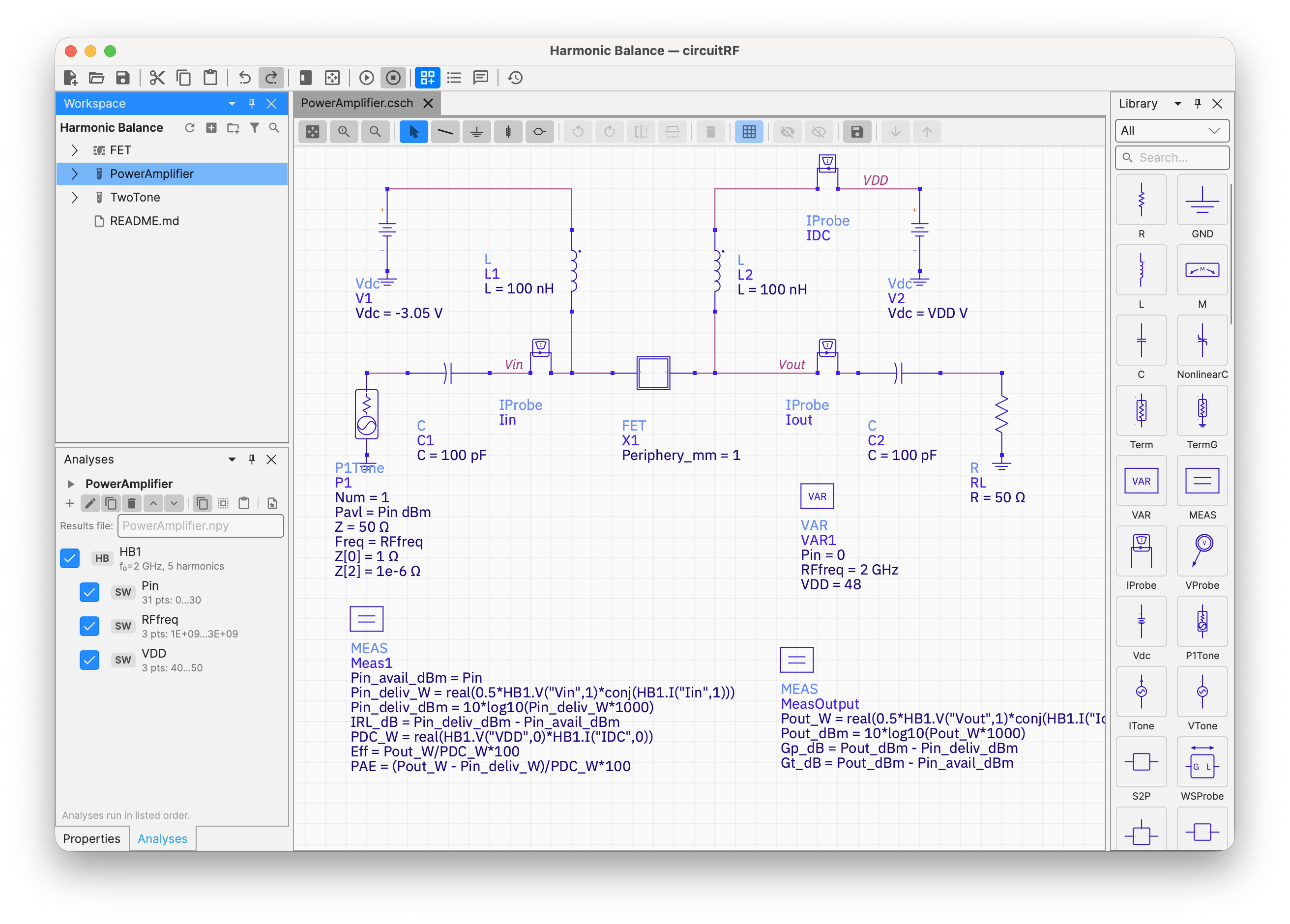
Build hierarchical RF circuits on a virtualized canvas: drag from the palette, wire, label nets, set
parameters and sweeps, and Run.
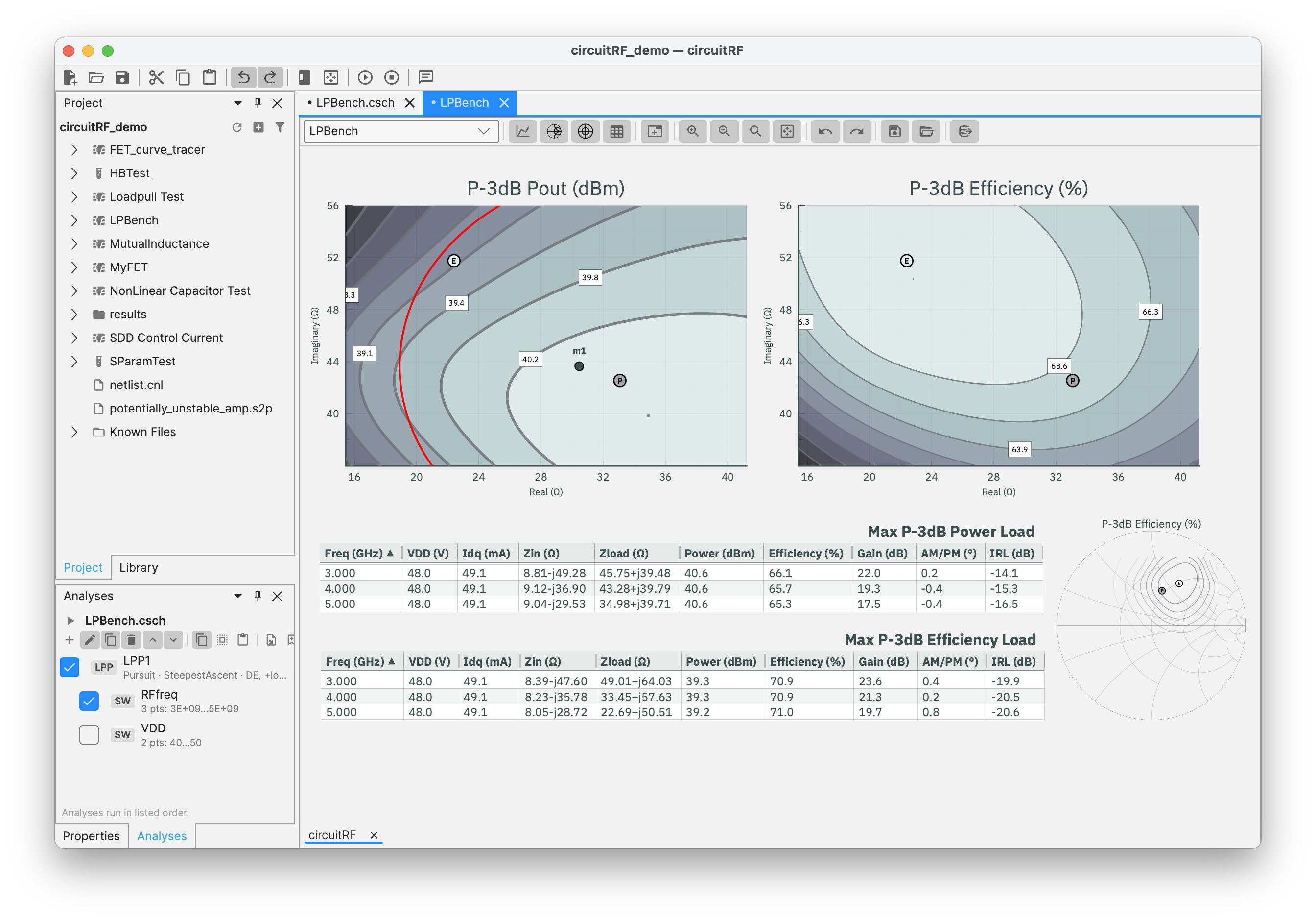
Data Display — loadpull contours
Plot S-parameters, spectra, power sweeps, and loadpull contours; overlay measured Touchstone/.spl/
.lpcwave data on simulated results; plot EM results from MoM, FEM and FDTD solvers (including radiation
patterns)
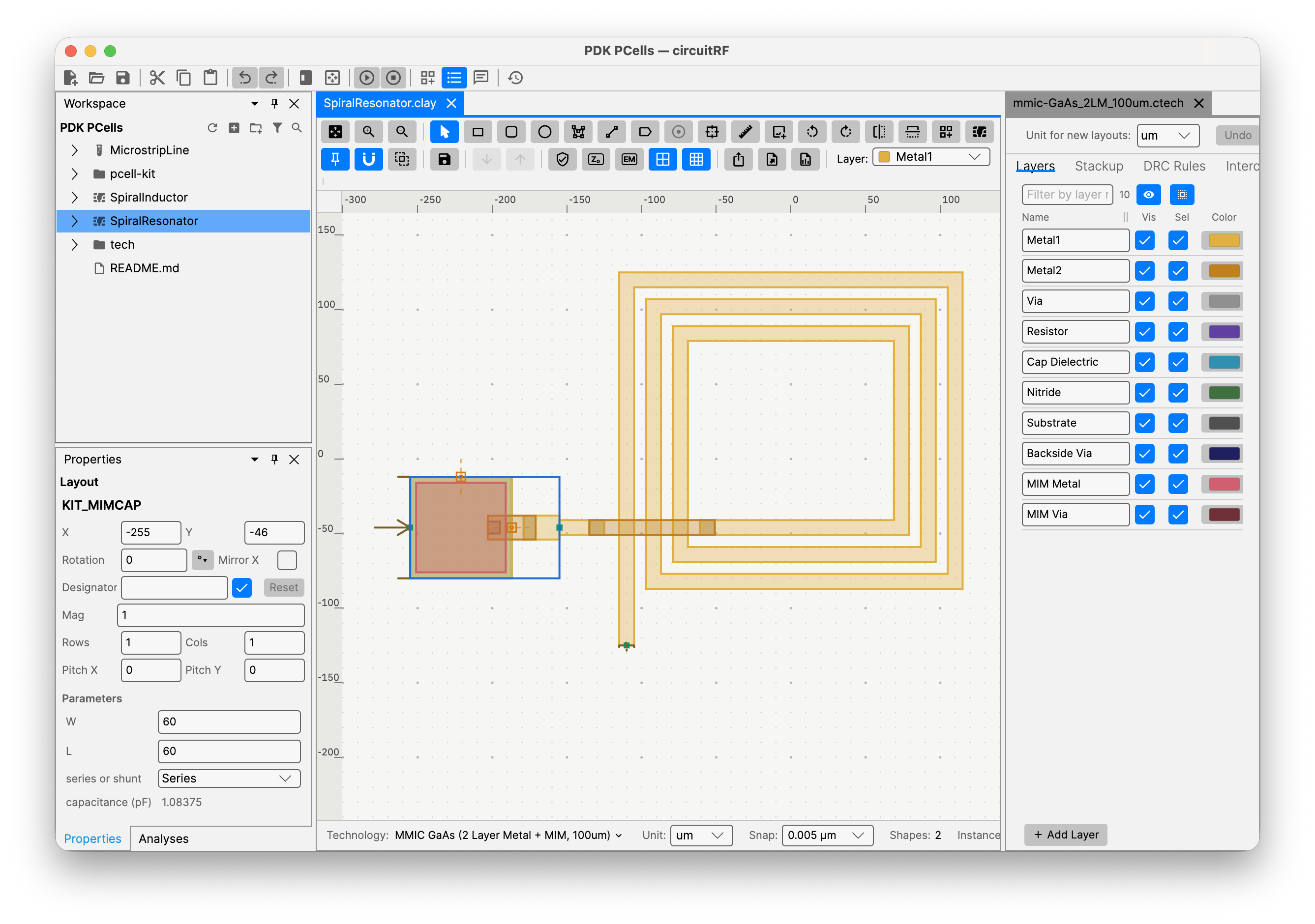
Layout editor
Draw and edit physical geometry on a technology-defined layer stack: microstrip components generated from
their schematic parameters, hierarchy with arrays, and export to GDSII, DXF and Gerber. MoM EM solver.
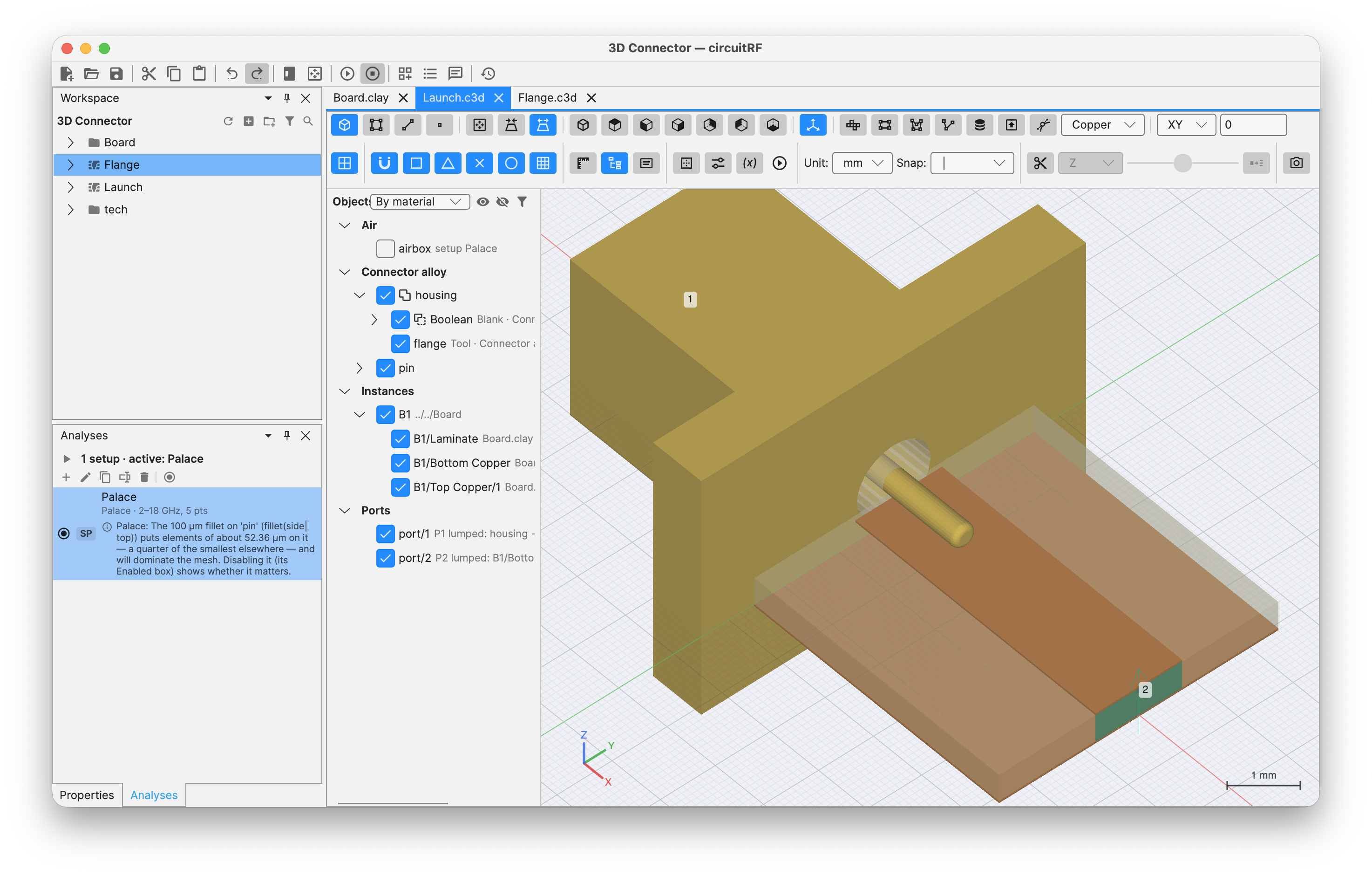
3D editor
Draw and edit in 3D and send to FEM or FDTD EM solvers or the built-in FEM thermal solver
Linux — unpack and run install.sh. It writes only inside ~/.local, puts circuitrf on your PATH
and registers the menu entry and file types; --uninstall removes it and leaves your work alone.
sh
tar xzf circuitRF-1.7.3-linux-x64.tar.gz
./circuitRF-1.7.3/install.sh
Linux AppImage: download it, make it executable (chmod +x circuitRF-1.7.3-linux-x64.AppImage)
and run it. Nothing is installed, so keep it wherever you like. It does not update itself: when a new
version is out, its line in the Messages panel has a Download button that saves the new AppImage
next to the one you are running. AppImageUpdate can update it too. Use the tarball if you want updates
installed automatically.
Installing for everyone on the machine? The Windows .msi files without -user, and the .deb
files, are on the releases page. They need
administrator rights, so they cannot update themselves — they tell you when a new version is out
instead.
Automatic updates can be turned off in Settings ▸ Security & Permissions. Building the installers
yourself: BUILDING.md.
Use circuitRF from an AI agent
circuitRF is also an MCP server, so an AI agent can create workspaces, write designs, check
them, run simulations and read the results back. The installed application is the server; there is
nothing else to install.
1. Pick a root folder. The server can read and write only inside it. Use the folder your
designs live in, such as ~/designs, not your whole home folder.
2. Ask circuitRF for its configuration. It prints the JSON an MCP client needs, with the
executable's full path filled in, and the matching Claude Code command:
3. Register it with your client. With Claude Code, run the claude mcp add … line it printed.
Most other clients take the printed JSON in their MCP settings. Start a new session afterwards,
because most clients load servers only when a session starts.
4. Check that it answers. Ask the agent to call circuitRF's reference tool. It should list
the reference topics.
Then read Designing with an AI agent, which covers what
to tell the agent, which reference topics it should read first, and the design flow that works. The
full server description, including running it from a source build, is in
The MCP Server.
Contributors are welcome — especially RF domain experts
circuitRF is meant to be community-driven, by and for the RF engineering community. We value RF
domain knowledge as much as software experience. If you design power amplifiers, LNAs, or mixers; build
RF EDA tooling; do device modeling; or develop transistor technology (GaN-on-SiC, GaN-on-Si, LDMOS, …),
you are exactly who this project needs — and circuitRF is a great place to use AI to build the
simulation features you want.
You do not need to be a professional software developer. If you've scripted in MATLAB or Python, you
have enough to start. Pair yourself with Claude Code (or your
AI assistant of choice) and let it do the heavy lifting on the C#.
Architecture
circuitRF is built in strictly one-directional layers, and nothing below the UI knows the UI
exists. The layers, the engines, the enforced framework firewall and the source tree are described in
ARCHITECTURE.md.
# cd to a working folder, then:
git clone https://github.com/potatobeanradio/circuitRF.git
3. Build and run
bash
cd circuitRF

dotnet build      # restores packages + compiles everything
dotnet run --project src/Ui # from the circuitRF/ directory:
For faster simulations, run the Release build: dotnet run --project src/Ui -c Release.
4. Optional — testing & building the device workers
bash
dotnet test # optional 10-15 min of circuitRF development tests
A handful of loadpull tests read lab-measured .spl/.lpcwave files that are third-party data held
under terms that do not permit redistribution, so they have never been committed here. On a fresh
clone those tests report as Skipped, naming the path they wanted — they never fail, and a fresh
clone is green without them. Your own measurements in either format, dropped at those paths, exercise
the same code.
To build the device workers:
Needed only for PDKs whose device models ship as compiled libraries. dotnet build builds the
workers itself if a C compiler is on PATH — with none, it warns and carries on, and such a kit
refuses at Run.
Install one, then rebuild:
powershell
winget install zig.zig # Windows (or: scoop install zig)
bash
brew install zig                            # macOS
sudo snap install zig --classic --beta      # Linux    (or your package manager)
bash
dotnet build
macOS also runs those Linux models in a VM circuitRF ships — one extra ~330 MB download, once:
Note: To package circuitRF as an app with installers
BUILDING.md has step-by-step instructions for producing the installers users
download: .msi (Windows x64/arm64/x86, per-machine and per-user), .zip (the Windows update
payload), .dmg (macOS arm64/x64), .deb (Linux x64/arm64) and .tar.gz (the Linux user-local
channel). One script per platform, run from the repository root.
Running circuitRF
To launch the GUI
bash
# from the circuitRF/ directory:
dotnet run --project src/Ui
# S-parameters: sweep 1-3 GHz in 50 MHz steps, write a Touchstone file
dotnet run --project src/Cli -- sparam mycircuit.cnl --freq 1GHz:3GHz:50MHz -o mycircuit.s2p

# DC operating point
dotnet run --project src/Cli -- dc mycircuit.cnl

# Harmonic balance (runs the parametric sweep, if one wraps the analysis)
dotnet run --project src/Cli -- hb hero2.cnl --set Pavl_dbm=0 -o hero2.npy

# Loadpull over the directive's Gamma grid, exported as loadpull interchange
dotnet run --project src/Cli -- lp hero3.cnl --pin -20:1:15 -o hero3.spl

# Loadpull pursuit: search for the max-power and max-efficiency terminations
dotnet run --project src/Cli -- lpp hero3B.cnl --out-grid found.gam -o hero3B.npy

# Electromagnetic extraction of the layout a .cem names — no other arguments needed
dotnet run --project src/Cli -- em Amp.cem

# Author a correct initial document: a workspace, then a cell inside it
dotnet run --project src/Cli -- new workspace ~/designs/Amp --tech pcb-4layer_FR-4_62mil_1oz
dotnet run --project src/Cli -- new cell ~/designs/Amp Stage1 --views schematic,symbol

# Bring artwork or a component in: one interchange format to another, or a part as a cell
dotnet run --project src/Cli -- convert Filter.dxf -o gerbers/
Run a netlist through an engine (in code)
The whole pipeline is three calls — read → elaborate → run — which is exactly what the CLI does:
csharp
using CircuitRF.Core.Netlist;
using CircuitRF.Core.Elaboration;
using CircuitRF.Engine;

var (lib, testbench) = CnlReader.ReadFile("mycircuit.cnl");
var netlist          = new Elaborator(lib).Elaborate(testbench);
var dataset          = SParameterEngine.Run(netlist, freqsHz);   // → a DataSet of DataCubes
What circuitRF doesn't do yet
Noise analysis — no noise figure, no phase noise, no Fmin / Γopt / Rn extraction.
Transient analysis — circuitRF is frequency-domain by design; there is no time-domain solver.
If you want to contribute to any of the above, please contact me.
User documentation
The user documentation — Quick Start, New User's Guide and Reference Guide — is published at
https://potatobeanradio.github.io/circuitRF/. It lives in docs/user/, is what
Help ▸ circuitRF Documentation opens, and is served online straight from this repository,
so the web pages and the shipped pages are the same bytes. It is generated, not hand-edited. By
default a run rebuilds every page and leaves every figure as committed; recapturing figures from the
live application is opt-in, because it is nearly all of a full run's time:
bash
dotnet run --project tools/DocGen -- --out docs/user                           # every page; figures as committed
dotnet run --project tools/DocGen -- --out docs/user --figures                 # ...and the figures of pages whose .md changed
dotnet run --project tools/DocGen -- --out docs/user --figure layout-editor    # ...and these figures, by name
dotnet run --project tools/DocGen -- --out docs/user --all-figures             # ...and every figure (minutes)
dotnet run --project tools/DocGen -- --page docs/user/src/reference/wbond.md   # just this page, in seconds
Prose is authored as Markdown under docs/user/src/; the pages under docs/user/ are the output and
any edit to one is reverted by the next run. Figures are vector captures of the running interface
— the generator opens circuitRF headlessly, drives real views with real content, and writes SVG — so
they cannot drift from the application. Component parameter tables come from the live registry for
the same reason. There are no screenshots in this documentation and there are not meant to be.
tools/DocGen/check-docs-current.sh regenerates everything, figures included, and diffs, and fails if the committed output is not
what the generator produces. Run it after a UI change that moves a figure. The design note is
docs/design/user-docs-factory.md.
Contributing
Contributions are welcome and encouraged. circuitRF is community-driven, by and for the RF community,
and RF domain knowledge counts as much as software experience. You don't need to be a career
programmer — MATLAB/Python scripting experience plus an AI assistant is plenty.
Good first contributions:
Report Issues
Use AI Agent to report issues, resolve them and initiate pull requests (PR)
The ground rules:
The architecture is layered and the UI firewall is enforced — keep Avalonia out of
RfCore/Core/Engine/Design/Cli/Harmonica/WBond (a CI test will catch you).
Renderers stay Skia-only.
Every numerical change needs a testdata/ regression test within the tolerance the PRD states.
The core is MIT — never ingest GPL code.
Each subsystem has a CLAUDE.md with its local conventions; read the relevant one before diving in.
Substantial issues or new features should be discussed before a large PR, so we can point you at the right design
note (and save you rework).
AI-assisted development
circuitRF was built largely with AI assistance (primarily Claude /
Claude Code), and AI-assisted contributions are first-class
here. The codebase is structured for it: spatial CLAUDE.md memory files capture the invariants and
local conventions of each subsystem, docs/design/ holds the reasoning behind each part, and
docs/skills/ holds step-by-step procedures you can hand directly to an AI agent.
This is the deliberate bet of the project: an RF expert with an AI assistant can build the simulation
features they need. If that describes you, you're in the right place.
License
circuitRF's own source code is released under the MIT License. A future commercial
superset, if any, layers on through a clean extension boundary without forking the core.
The distribution also contains third-party components under their own terms, inventoried in
THIRD-PARTY-NOTICES.md. Three of them are copyleft and worth knowing about
before you redistribute a build:
CSparse.NET (sparse complex LU, used throughout the engine)
is LGPL-2.1-only. The packaged installers link it statically, so LGPL §6's relink requirement
applies — satisfied here by publishing complete source, since anyone can substitute a modified
CSparse.NET and rebuild. If you redistribute circuitRF binaries, that obligation travels with them.
Open CASCADE Technology (the geometry kernel behind
booleans, fillets and STEP, run by tools/geometry-worker) is LGPL-2.1-only with the Open CASCADE
Exception. The installers carry it unmodified as shared libraries in one replaceable folder, and
its source is available under the written offer in the notices. The repository holds none of it:
building from source fetches it with the recipe in tools/geometry-worker/occt/.
No strong-copyleft (GPL/AGPL) code is ingested, and none is planned — see CLAUDE.md for the standing
rule on learning from GPL simulators without copying them.
Open CASCADE Technology (geometry kernel — LGPL-2.1-only with the Open CASCADE Exception 1.0); circuitRF uses facilities provided by Open CASCADE Technology
Clipper2 (integer-coordinate polygon clipping and offsetting, used by the layout editor — Boost Software License)
gdstk (OASIS and GDSII reading and writing for the (gdstk) import and export commands, run by tools/gdstk-worker — Boost Software License), with its bundled Clipper 6.4.2 (Boost Software License), Qhull (Qhull licence) and zlib (zlib licence), all linked statically into the one worker program
Full featured RF circuit + electromagnetic simulator. DC, S-parameters, harmonic balance, loadpull, envelope. Also supports 2D and 3D layout and design and electromagnetic MoM, FEM, FDTD + thermal FEM.
Full featured RF circuit + electromagnetic simulator. DC, S-parameters, harmonic balance, loadpull, envelope. Also supports 2D and 3D layout and design and electromagnetic MoM, FEM, FDTD + thermal FEM.
KiCad plugin for automatic keyboard's key placement and routing
9 parts547GPL-3.0
Questions
What parts does the Two sided use?
9 parts. The full list of its parts is on this page, with links to each part's symbol and footprint where PCBKit's library has them.
Where can I download the Two sided KiCad files?
From the potatobeanradio/circuitRF repository on GitHub, at the commit this page was made from: the board is testdata/pcb-samples/two-sided.kicad_pcb and its schematic testdata/schematic-import/sexpr/divider.kicad_sch. PCBKit opens the board in the browser, with nothing to install.
Can I use the Two sided design in my own project?
Its repository publishes it under the MIT licence: you may reuse it on that licence's terms (keep the author's notice, and for a copyleft licence share your changes alike).




 Draw and edit in 3D and send to FEM or FDTD EM solvers or the built-in FEM thermal solver


