2 layers

 postfalk/z808
See BASICDEBUG2026-04-11.md for a summary of:
Z80uart is an open-source printed circuit board by postfalk, from the postfalk/z80 repository on GitHub. It is a 2-layer board with 7 parts on 69 nets, routed with 216 tracks and 45 vias.
Its parts include 4 ICs, 2 capacitors and 1 crystal.
See BASIC_DEBUG_2026-04-11.md for a summary of:
zasm vs z80asm)#My Z80 Computer
There is a Z80 assembler in the Ubuntu universe repos!!!
sudo apt-get install z80asm Make sure z80asm is in your executable path. There is also a de-assembler for binaries (z80dasm).
I wrote a simple Python script to automate assembly.
python assemble.py -i test.asmIn order to review binary hex code install bless:
sudo apt-get install blessMost software and examples are written in TASM, I found a compatible project still maintained called ZASM
http://k1.spdns.de/Develop/Projects/zasm/Distributions/
CPM setup
This page proved very useful
http://cpuville.com/cpm_on_new_computer.html
(Currently validating its usefulness)
------------- Much of the below is now obsolete ------------------
Arduino driven Z80 development
The Arduino is gone now. Development is fun without it. However, the form factor is still there. Arduino could be used for debugging as needed.
The basic idea of this project is to use an Arduino to support the development of a z80 computer system and debug any of its components in the process. The Arduino stands in as ...
a) reset generator
b) clock
c) ROM for the lowest 64byte 0000h-003Fh
The z80 code is fed from a C array to PORTD, PORTB (with 6pins on an Arduino UNO R3) as address bus, and PORTC simulates the control bus (RD --> PIN4, MRQ --> PIN2, RESET <-- PIN3, CLOCK <-- Pin5). The array index correspondends directly with the z80 system address.
The z80 board is more or less configured as an Arduino shield (even though bigger, the Arduino is plucked in upside down on top of it). In order to run the board without the Arduino, I created a circuit on an Arduino shield PCB with the reset and clock circuit. Thus, it is possible to go back and forth between normal computer operation and running debug code from Arduino.
The Arduino emulation runs somewhat over 600khz after stripping all pinMode routines out of the Arduino code. (I wonder whether the if ... else ... control structure could be replaced with bitwise logic as well).
After Arduino reset, the Aruino code will perform a z80 reset as well (which needs at least 4 clock cycles).
~~The clock speed can be modified by nserting Arduino delays in the code which is very useful for debugging. Serial.println proved also very useful even though it might conflict with z80 data bus on PORT D. For this reason it needs to be placed strategically (e.g. at the high phase of the clock cycle).
A new idea is to use the Arduino as a simple IO device at the Z80 bus. At a 4Mhz clock it would require to use the WAIT signal.
Prerequisites
EEPROM
I got a very cheap, very universal EEPROM programmer called MiniPro TL866xx. It works perfectly with following project: Install the project if you want to use this project to directly write XPROMS with the code below.
Tested with [XICOR 28C64] (https://www.jameco.com/Jameco/Products/ProdDS/74827.pdf). The python code below assumes this 8k by 8byte device. Change code accordingly for other devices or more flexible use.
Example use:
minipro -p X28C64 -w d88_rom.binRAM
http://ee-classes.usc.edu/ee459/library/datasheets/628128.pdf
Current configuration
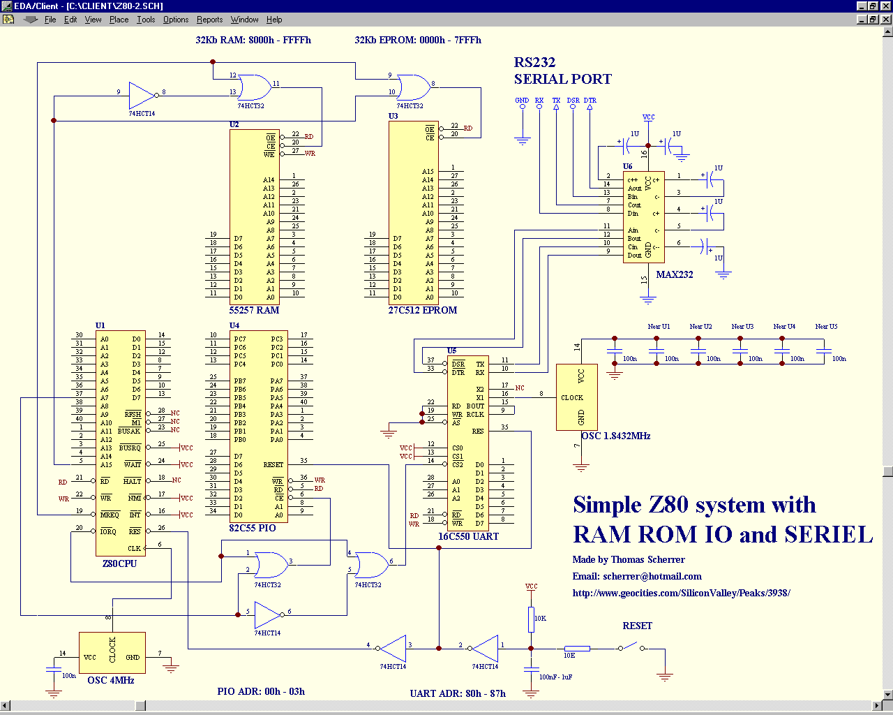
The circuit follows very closely http://www.z80.info/gfx/z80test.gif.
Differences:
Addresses:
Memory:
0000h - 003Fh Arduino ROM emulation
or
0000h - 7FFFh Space for ROM
8000h - FFFFh (static) RAM
I/O:
00h - 03h PIO
00h PORT A - ctrl
01h PORT A - data
02h PORT B - ctrl
03h PORT B - data
80h - 87h UART - TL16C550A, documentation: http://www.pci-card.com/TL16C550.pdf
Using the 74HCT138 for address decoding we can address 8 devices (2 of the lines are still unused). The wiring is a little bit unusual here: A - A7, B - A6, C - A5
Example code in this project
piobasics.asm
Just turns bit 0 at port B on if addresses are configured as above. (any speed, originally 1 to 10hz :) )
pioextended.asm
Blinks bit 0 at port B if addresses are configured as above (optimized for, i.e. visible at 600kHz clock). Also requires RAM at ffffh for sub routine call.
d88.asm
A somewhat unsuccessful attempt to drive a I2C 8x8 LED display from Adafruit. The program is able to output a "picture". However, the module used requires continous I2C clock which is hard to provide without timer interrupt. Might pick this project up once CTC interupts are available.
serial.asm
Basic implementation of a serial communixcation. Minimal working (output) setup using 9600-8-N-1 configuration:
To set the baud rate, we need to access the divisor registers, which is done by setting the most significant bit of the line control register to 1.
set register 83 to 80 (1000 0000)
now set dividers:
set register 80h to 0ch (12 for 9600)
set register 81h to 00h
now configure line control register
set register 83h to 03h
now transmit data by setting value of register 80h
check register 85h bit 4 will tell whether transmission register is clear
bootloader.asm
load file from serial port
assembled code needs to start on 0800h
file end is determined by time out
jump to start program
keyboard.asm
simple serial reflector of keyboard activity
load with bootloader
Documentation Links
[Zilog User Manual] (http://www.z80.info/zip/z80cpu_um.pdf)
###Explore
http://www.ecstaticlyrics.com/electronics/SPI/fast_z80_interface.html
CPM 2.2 installation: This looks pretty reasonable. I like the idea to use an actual IDE hard disk and do not care about its compatibility outside the system.
[http://www.glynstore.com/content/docs/ftdi/DS_VDIP2.pdf]: Explore this option to get USB sticks and FAT32 going relatively easily and somewhat lame.
| Qty | Value | Footprint | References |
|---|---|---|---|
| 2 | 100nF | Capacitors_ThroughHole:C_Disc_D3_P2.5 | C1, C2 |
| 1 | 16550 | Housings_DIP:DIP-40_W15.24mm | U1 |
| 1 | 74LS238 | Housings_DIP:DIP-16_W7.62mm | U2 |
| 1 | XO-14S | Oscillators:KXO-200 | X1 |
| 1 | serial_port_interface | kicad:serial_to_usb_large | U100 |
| 1 | z80pcb | kicad:z80systemboard | U101 |
7 parts. The full list of its parts is on this page, with links to each part's symbol and footprint where PCBKit's library has them.
From the postfalk/z80 repository on GitHub, at the commit this page was made from: the board is kicad/z80uart/z80uart.kicad_pcb. PCBKit opens the board in the browser, with nothing to install.
Its repository states no licence, so its author keeps all rights: ask postfalk before reusing the design.


byrantech/laptop
anyon_e, a highly integrated, high end, open source laptop. Attempt the impossible.


AxxAxx/AxxSolder
STM32 Based soldering station for JBC cartridges, 9-24 VDC and USB-PD power


jamro/tiny-engineer
A small desktop robot that brings an AI coding assistant to life, physically acting out when it reads files, thinks, writes code, and finishes work.

hoglet67/RGBtoHDMI
Bare-metal Raspberry Pi project that provides pixel-perfect sampling of Retro Computer RGB/YUV video and conversion to HDMI
