
2 layers20.3 × 28.6 mm

 portlandrobotics/common_platform10
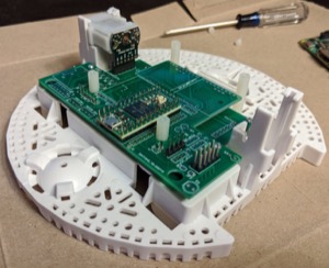
Romi board is an open-source printed circuit board by portlandrobotics, from the portlandrobotics/common_platform repository on GitHub. It is a 2-layer board of 107 × 70 mm with 51 parts on 61 nets, routed with 678 tracks and 68 vias.
It is built around the TB9051FTG,EL. Its parts include 9 resistors, 4 connectors, 2 capacitors, 2 transistors and 2 switches. It belongs with the NXP (LPC, Kinetis, i.MX RT) boards of this library.
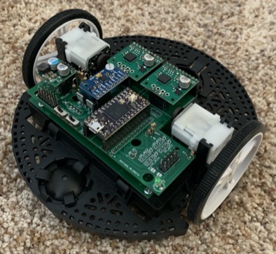
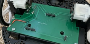
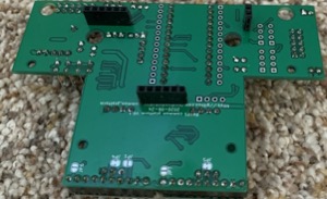
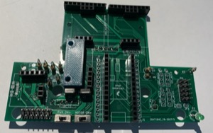
| Qty | Value | Footprint | References |
|---|---|---|---|
| 5 | 4.7K | Resistor_THT:R_Axial_DIN0309_L9.0mm_D3.2mm_P2.54mm_Vertical | R4, R5, R7, R8, R9 |
| 5 | Conn_01x04 | Connector_PinHeader_2.54mm:PinHeader_1x04_P2.54mm_Vertical | I2C_ACC1, I2C_ACC2, I2C_ACC3, I2C_ACC4, ULTRASONIC1 |
| 5 | SolderJumper_2_Open | Jumper:SolderJumper-2_P1.3mm_Open_RoundedPad1.0x1.5mm | JP1, JP2, JP3, JP6, JP7 |
| 4 | MountingHole | MountingHole:MountingHole_2.5mm | H1, H2, H3, H4 |
| 4 | MountingHole | teensy:MountingHole_6mm_passthrough | H5, H6, H7, H8 |
| 2 | Conn_01x14 | Connector_PinHeader_2.54mm:PinHeader_1x14_P2.54mm_Vertical | J1, J2 |
| 2 | Q_PMOS_DGS | Package_TO_SOT_THT:TO-251-3_Vertical | Q1, Q2 |
| 2 | SW_SPDT | teensy:Switch | SW1, SW2 |
| 2 | SolderJumper_2_Bridged | Jumper:SolderJumper-2_P1.3mm_Bridged_RoundedPad1.0x1.5mm | JP4, JP5 |
| 2 | TB9051FTG | teensy:TB9051FTG_db | DRV_LEFT1, DRV_RIGHT1 |
| 2 | TestPoint | TestPoint:TestPoint_Pad_D2.0mm | TP1, TP2 |
| 1 | 0.1u | Capacitor_THT:C_Disc_D5.0mm_W2.5mm_P5.00mm | C1 |
| 1 | 1K | Resistor_THT:R_Axial_DIN0309_L9.0mm_D3.2mm_P2.54mm_Vertical | R3 |
| 1 | 1M | Resistor_THT:R_Axial_DIN0309_L9.0mm_D3.2mm_P2.54mm_Vertical | R2 |
| 1 | 2M | Resistor_THT:R_Axial_DIN0309_L9.0mm_D3.2mm_P2.54mm_Vertical | R1 |
| 1 | 3.3K | Resistor_THT:R_Axial_DIN0309_L9.0mm_D3.2mm_P2.54mm_Vertical | R6 |
| 1 | 470u | Capacitor_THT:CP_Radial_D6.3mm_P2.50mm | C2 |
| 1 | Conn_01x04 | Connector_PinHeader_2.54mm:PinHeader_1x02_P2.54mm_Vertical | C_IBC_R1 |
| 1 | Conn_01x04 | teensy:MPU9250_BB | IMU-9250 |
| 1 | Conn_01x06 | Connector_PinHeader_2.54mm:PinHeader_1x06_P2.54mm_Vertical | C_IBC_L1 |
| 1 | Conn_01x07 | Connector_PinHeader_2.54mm:PinHeader_1x06_P2.54mm_Vertical | C_IBC_T1 |
| 1 | Conn_02x06_Odd_Even | Connector_PinHeader_2.54mm:PinHeader_2x06_P2.54mm_Vertical | J3 |
| 1 | D24V22F5 | teensy:D24V2F5_bb | REG_5V1 |
| 1 | LED | LED_THT:LED_D5.0mm | D1 |
| 1 | RASPBERRY_PI_GPIO | Connector_PinHeader_2.54mm:PinHeader_2x05_P2.54mm_Vertical | PI1 |
| 1 | Teensy4.0 | teensy:Teensy40_simple | U1 |
| 1 | USB_B_Micro | Connector_USB:USB_Micro-B_Molex_47346-0001 | J4 |


kitspace-test-repos/kicad6-file-collection

davidphilipbarr/Sweep
Sweep - a small promicro based keyboard inspired by the Ferris.


W0rthlessS0ul/nRF24_jammer
The nRF24 jammer is a powerful tool that requires an ESP32 and configurable numbers of NRF24 modules to assemble.

hackclub/OnBoard
💡 Join 1,000 teenagers and make your first PCB with a $100 grant!


Neumi/open_echo
Open Source echo sounder / depth sounder / SONAR for bathymetry and research. Arduino based and compatible.

It measures 107 × 70 mm and has 2 copper layers, 1.6 mm thick.
51 parts, built around the TB9051FTG,EL. The full list of its parts is on this page, with links to each part's symbol and footprint where PCBKit's library has them.
From the portlandrobotics/common_platform repository on GitHub, at the commit this page was made from: the board is hardware/romi_board/romi_board.kicad_pcb and its schematic hardware/romi_board/romi_board.kicad_sch. PCBKit opens the board in the browser, with nothing to install.
Its repository states no licence, so its author keeps all rights: ask portlandrobotics before reusing the design.