

2 layers183.9 × 111.3 mm
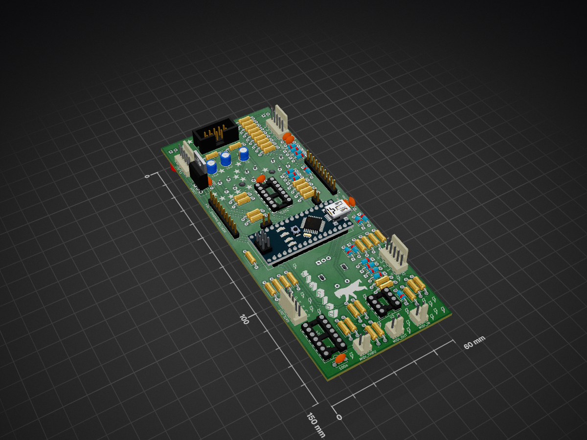
 polykit/kosmo-multitool31
Arduino Nano Every based development platform for DIY synthesizer enthusiasts.
Kosmo multitool is an open-source printed circuit board by polykit, from the polykit/kosmo-multitool repository on GitHub. It is a 2-layer board of 60 × 150 mm with 131 parts on 81 nets, routed with 417 tracks and 8 vias.
It is built around the 74LS14PC and L7805. Its parts include 37 resistors, 19 diodes, 12 connectors, 10 capacitors and 4 ICs. It belongs with the audio and music boards of this library.
This repository contains schematics, PCB and source code for a synthesizer module in Kosmo format. This module consists of an Arduino Nano Every, CV and gate input and output options, MIDI, rotary encoder and an OLED display. It is meant as a development platform for DIY synthesizer enthusiasts.
Here is a full list of features:
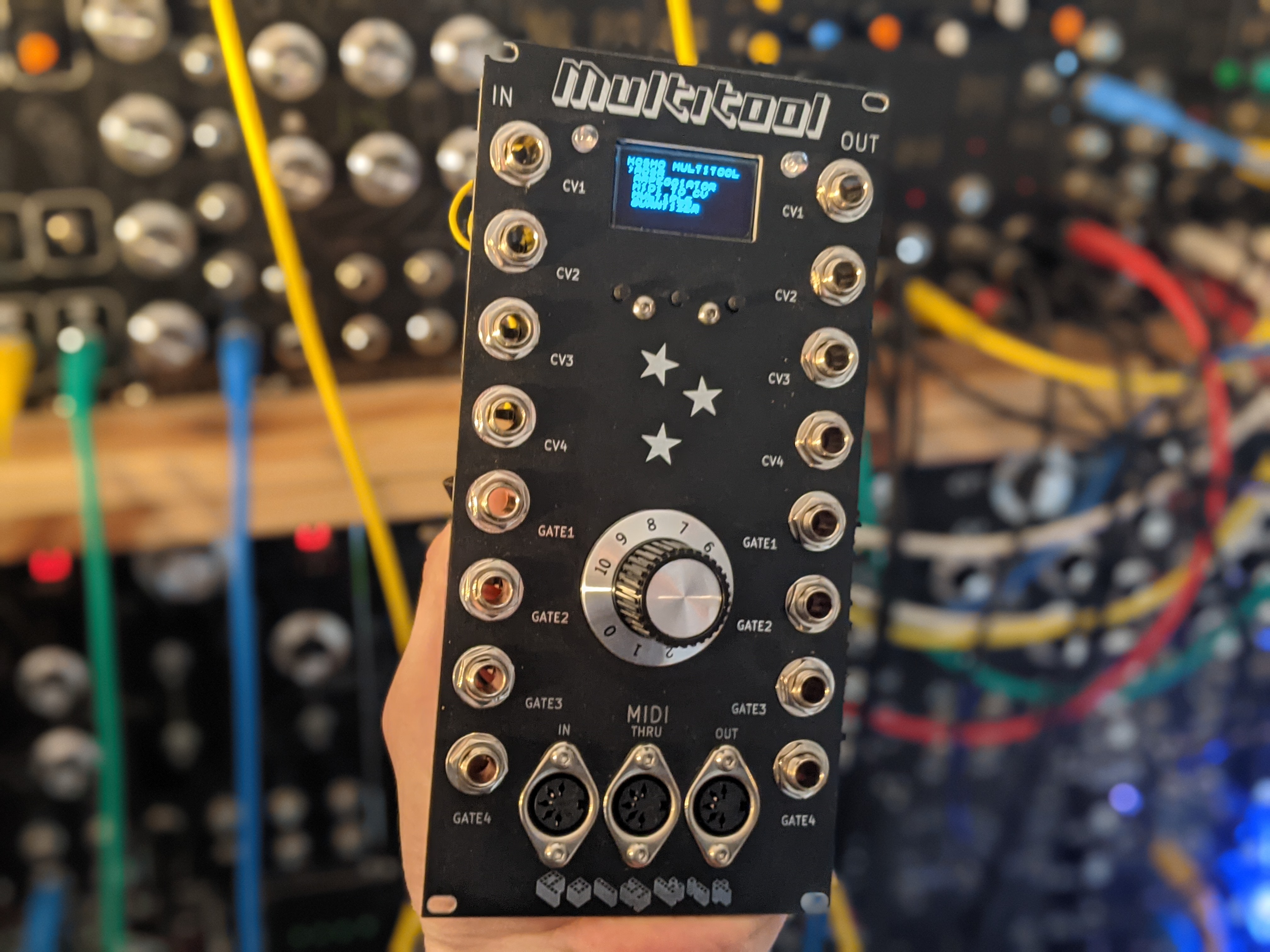
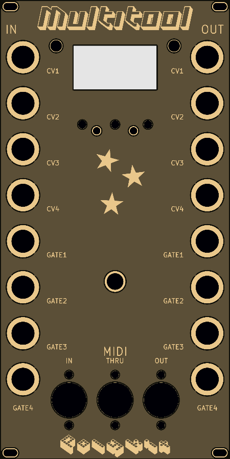
Gerbers for the main PCB can be found here and for the front panel here.
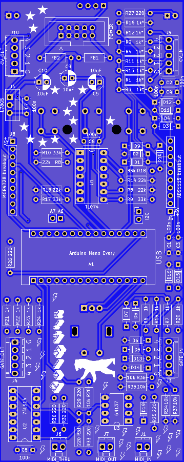
| Reference | Quantity | Value | Comment |
|---|---|---|---|
| A1 | 1 | Arduino Nano Every | |
| C1 C2 C3 C4 C6 C7 C8 | 7 | 100n | |
| C5 C9 C10 | 3 | 10uF | |
| D17 D18 | 2 | LED 5mm | |
| D1 D2 D3 D4 D5 D6 D7 D8 D9 D10 D11 D12 D13 D14 D15 D16 D19 | 17 | 1N4148 | |
| FB1 FB2 | 2 | Ferrite Bead | |
| J1 | 1 | MIDI_IN | Molex KK 2.54mm 2 pin |
| J10 | 1 | CV_OUT | Molex KK 2.54mm 5 pin |
| J2 | 1 | Display I2C | OLED display 1.3" 128x64 I2C SH1106 |
| J3 | 1 | GATE_IN | Molex KK 2.54mm 5 pin |
| J4 | 1 | GATE_OUT | Molex KK 2.54mm 5 pin |
| J5 | 1 | ADS1115 breakout | ADC, pin order: VCC GND SCL SDA ADDR ALERT A B C D |
| J6 | 1 | MIDI_THRU | Molex KK 2.54mm 2 pin |
| J7 | 1 | MIDI_OUT | Molex KK 2.54mm 2 pin |
| J8 | 1 | MCP4728 breakout | DAC, pin order: VCC GND SCL SDA LDAC READY A B C D |
| J9 | 1 | CV_IN | Molex KK 2.54mm 5 pin |
| POWER1 | 1 | POWER | IDC 10 pin |
| R1 R2 R3 R4 R11 R12 R15 R16 | 8 | 1k* | |
| R5 R8 R13 R14 | 4 | 22k | |
| R9 R10 R17 R18 | 4 | 33k | |
| R25 R26 R27 R29 R30 R31 R32 R33 | 8 | 220 | |
| R28 R34 R35 R36 R37 | 5 | 10k | |
| R6 R7 R19 R20 R21 R22 R23 R24 | 8 | 1k | |
| SW1 SW2 SW3 | 3 | SW_Push | Tactile Push Button 6x6x15mm |
| SW4 | 1 | Rotary_Encoder_Switch | Rotary encoder with switch, 20mm |
| U1 | 1 | TL074 | |
| U2 | 1 | 74LS14 | |
| U3 | 1 | 6N137 | |
| U4 | 1 | L7805 | |
| Pin sockets, 2.54mm | Needed for the Arduino, OLED display, ADC and DAC | ||
| 16 | Jack sockets 6.35mm | ||
| 3 | DIN MIDI sockets |
* match in pairs to get more accurate ADC readings
Clone the repository and open up the src/main folder in the Arduino IDE or whatever you use for compiling. You need to install the libraries mentioned below into you Arduino library folder. The ADC and the DAC need calibration to get proper results.
Set CALIBRATE_CV_IN variable in main file to 1. Apply a fixed, known voltage to CV1 input, eg. 5.000V. On USB serial console (9600 baud) you get the actual reading from the ADC. Calculate the correction factor FIXED VOLTAGE / ACTUAL VOLTAGE, eg. 5.000 / 4.9884 = 1.0023. Enter the value in the CV_IN_CORRECTION array in the top lines of main.ino. Repeat this procedure for all CV inputs. In the end it should look something like this:
float CV_IN_CORRECTION[4] = {0.9995f, 0.9956f, 1.0013f, 1.0009f};Notice the trailing f to tell the compiler that these are float values. Don't forget to set CALIBRATE_CV_IN back to 0.
Make sure to calibrate the ADC first. Set CALIBRATE_CV_OUT variable in main file to 1. Plug in patch cables from all four CV inputs to the CV outputs. Calibration is done automatically and stored in a look-up table. Set CALIBRATE_CV_OUT back to 0. This step is only needed once, from now on calibration values are loaded from EEPROM on start up.
Source code is in src/main. If you want to develop your own module just copy the files example_module.h and example_module.ino and rename all functions and variables that are globally available. Include your header file in the main.ino file and add your entry to the main menu. Take a look at the already existing modules on how it works in general. If you created a nice module please file a pull request and I would be happy to merge it.
https://github.com/adafruit/Adafruit_MCP4728
https://github.com/adafruit/Adafruit_ADS1X15
https://github.com/olikraus/u8g2
https://github.com/FortySevenEffects/arduino_midi_library
https://github.com/neu-rah/ArduinoMenu
https://github.com/thomasfredericks/Bounce2
https://github.com/mathertel/RotaryEncoder
https://github.com/ivanseidel/LinkedList
https://www.lookmumnocomputer.com/modular
https://www.ti.com/lit/ds/symlink/ads1115.pdf
http://ww1.microchip.com/downloads/en/devicedoc/22187e.pdf
https://github.com/DylanMeeus/GoAudio
This work is licensed under a Creative Commons Attribution-NonCommercial 4.0 International License.
| Qty | Value | Footprint | References |
|---|---|---|---|
| 21 | LOGO | Polykit:blitz-silk-supertiny | G***, G***, G***, G***, G***, G***, G***, G***, G***, G***, G***, G***, G***, G***, G***, G*** +5 |
| 17 | 1N4148 | Diode_THT:D_DO-35_SOD27_P7.62mm_Horizontal | D1, D2, D3, D4, D5, D6, D7, D8, D10, D11, D12, D13, D14, D15, D16, D19 +1 |
| 14 | LOGO | Polykit:star-silk-tiny | G***, G***, G***, G***, G***, G***, G***, G***, G***, G***, G***, G***, G***, G*** |
| 8 | 1k | Resistor_THT:R_Axial_DIN0207_L6.3mm_D2.5mm_P10.16mm_Horizontal | R6, R7, R19, R20, R21, R22, R23, R24 |
| 8 | 1k* | Resistor_THT:R_Axial_DIN0207_L6.3mm_D2.5mm_P10.16mm_Horizontal | R1, R2, R3, R4, R11, R12, R15, R16 |
| 8 | 220 | Resistor_THT:R_Axial_DIN0207_L6.3mm_D2.5mm_P10.16mm_Horizontal | R25, R26, R27, R29, R30, R31, R32, R33 |
| 7 | 100n | Capacitor_THT:C_Disc_D5.0mm_W2.5mm_P5.00mm | C1, C2, C3, C4, C6, C7, C8 |
| 5 | 10k | Resistor_THT:R_Axial_DIN0207_L6.3mm_D2.5mm_P10.16mm_Horizontal | R28, R34, R35, R36, R37 |
| 4 | 22k | Resistor_THT:R_Axial_DIN0207_L6.3mm_D2.5mm_P10.16mm_Horizontal | R5, R8, R13, R14 |
| 4 | 33k | Resistor_THT:R_Axial_DIN0207_L6.3mm_D2.5mm_P10.16mm_Horizontal | R9, R10, R17, R18 |
| 3 | 10uF | Capacitor_THT:CP_Radial_D5.0mm_P2.50mm | C5, C9, C10 |
| 3 | SW_Push | Button_Switch_THT:SW_PUSH_6mm_H13mm | SW1, SW2, SW3 |
| 2 | Ferrite_Bead | Resistor_THT:R_Axial_DIN0207_L6.3mm_D2.5mm_P10.16mm_Horizontal | FB1, FB2 |
| 2 | LED | LED_THT:LED_D5.0mm | D17, D18 |
| 2 | LOGO | Polykit:logo-silk-2.5cm | G***, G*** |
| 2 | LOGO | Polykit:bär | G***, G*** |
| 1 | 6N137 | Package_DIP:DIP-8_W7.62mm_Socket_LongPads | U3 |
| 1 | 74LS14 | Package_DIP:DIP-14_W7.62mm_Socket_LongPads | U2 |
| 1 | A7 A6 | Connector_PinHeader_2.54mm:PinHeader_1x02_P2.54mm_Vertical | J12 |
| 1 | ADS1115 breakout | Connector_PinHeader_2.54mm:PinHeader_1x10_P2.54mm_Vertical | J5 |
| 1 | Arduino Nano Every | Module:Arduino_Nano | A1 |
| 1 | CV_IN | Connector_Molex:Molex_KK-254_AE-6410-05A_1x05_P2.54mm_Vertical | J9 |
| 1 | CV_OUT | Connector_Molex:Molex_KK-254_AE-6410-05A_1x05_P2.54mm_Vertical | J10 |
| 1 | Display I2C | Connector_PinHeader_2.54mm:PinHeader_1x04_P2.54mm_Vertical | J2 |
| 1 | GATE_IN | Connector_Molex:Molex_KK-254_AE-6410-05A_1x05_P2.54mm_Vertical | J3 |
| 1 | GATE_OUT | Connector_Molex:Molex_KK-254_AE-6410-05A_1x05_P2.54mm_Vertical | J4 |
| 1 | I2C | Connector_PinHeader_2.54mm:PinHeader_1x02_P2.54mm_Vertical | J11 |
| 1 | L7805 | Package_TO_SOT_THT:TO-220-3_Vertical | U4 |
| 1 | LOGO | Polykit:star-silk | G*** |
| 1 | LOGO | Polykit:blitz-silk-small | G*** |
| 1 | MCP4728 breakout | Connector_PinHeader_2.54mm:PinHeader_1x10_P2.54mm_Vertical | J8 |
| 1 | MIDI_IN | Connector_Molex:Molex_KK-254_AE-6410-02A_1x02_P2.54mm_Vertical | J1 |
| 1 | MIDI_OUT | Connector_Molex:Molex_KK-254_AE-6410-02A_1x02_P2.54mm_Vertical | J7 |
| 1 | MIDI_THRU | Connector_Molex:Molex_KK-254_AE-6410-02A_1x02_P2.54mm_Vertical | J6 |
| 1 | POWER | Connector_IDC:IDC-Header_2x05_P2.54mm_Vertical | POWER1 |
| 1 | Rotary_Encoder_Switch | Rotary_Encoder:RotaryEncoder_Alps_EC11E-Switch_Vertical_H20mm | SW4 |
| 1 | TL074 | Package_DIP:DIP-14_W7.62mm_Socket_LongPads | U1 |
It measures 60 × 150 mm and has 2 copper layers, 1.6 mm thick.
131 parts, built around the 74LS14PC and L7805. The full list of its parts is on this page, with links to each part's symbol and footprint where PCBKit's library has them.
From the polykit/kosmo-multitool repository on GitHub, at the commit this page was made from: the board is kosmo-multitool.kicad_pcb. PCBKit opens the board in the browser, with nothing to install.
Its repository states no licence, so its author keeps all rights: ask polykit before reusing the design.


Andy18650/GB2-2025-team4
GitHub repository for Cambridge University Engineering part IIA project GB2: Electrical Power, Team 4

computerguy096/snark-barker-mini
A miniaturized version of the Snark Barker


hprd/z80-fpga-drop-in-replacement
UT Austin Fall 2025-Spring 2026 Senior Design Project for developing a Zilog Z80 CPU drop-in replacement using an FPGA.


schlae/comix-35
The COMIX-35 is an improved clone of the COMX-35 1802 home computer