4 layers32.4 × 38.1 mm
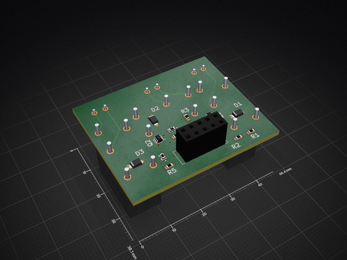
 polrolnik2/Smart-Home-Modular
Relay Module Project is an open-source printed circuit board by polrolnik2, from the polrolnik2/Smart-Home-Modular repository on GitHub. It is a 2-layer board of 46.4 × 38.1 mm with 20 parts on 25 nets, routed with 176 tracks and 10 vias.
It is built around the 1N4448W-7-FS, T50201500000G and SSM6N7002CFU,LF, with the SSW-105-01-T-D among its other parts. Its parts include 8 resistors, 4 connectors, 3 diodes, 3 switches and 2 transistors. It belongs with the home automation and IoT boards of this library.


| Qty | Value | Footprint | References |
|---|---|---|---|
| 4 | ERJ-3GEYJ103V | ERJ-3GEYJ103V:RESC1608X55N | R1, R3, R4, R5 |
| 3 | 1N4448W-7-F | 1N4448W-7-F:SOD3716X145N | D1, D2, D3 |
| 3 | ERJ-3EKF2000V | ERJ-3EKF2000V:ERJ3EK_(0603) | R6, R7, R8 |
| 3 | G5Q-14_DC9 | G5Q-14 DC9_n:G5Q-14 DC9 | K1, K2, K3 |
| 3 | T50201500000G | T50201500000G:T50201500000G | J2, J3, J4 |
| 2 | SSM6N7002CFU,LF | SamacSys_Parts:SSOP6-P-0.65A_US6_ | Q1, Q2 |
| 1 | ERJ-3GEYJ203V | ERJ-3GEYJ103V:RESC1608X55N | R2 |
| 1 | SSW-105-01-T-D | SSW-105-01-T-D:SSW10501TD | J1 |
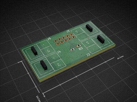


bsiyoung/FPGA_Pre_Test
Testing power rails and oscillator waveforms for FPGA use.

GuilleGonzzalez/hw-thingcell
Firmware used in this device is fw-thingcell, a custom made firmware implemented using Arduino Home Assistant Arduino library (docs).


atopile/atopile
Design circuit boards with code! ✨ Get software-like design reuse 🚀, validation, version control and collaboration in hardware; starting with electronics ⚡️

davidphilipbarr/Sweep
Sweep - a small promicro based keyboard inspired by the Ferris.

rusefi/rusefi
rusefi - GPL internal combustion engine control unit
It measures 46.4 × 38.1 mm and has 2 copper layers, 1.6 mm thick.
20 parts, built around the 1N4448W-7-FS, T50201500000G, SSM6N7002CFU,LF and SSW-105-01-T-D. The full list of its parts is on this page, with links to each part's symbol and footprint where PCBKit's library has them.
From the polrolnik2/Smart-Home-Modular repository on GitHub, at the commit this page was made from: the board is Modules/Relay_Module/Relay_Module_Project/Relay_Module_Project.kicad_pcb and its schematic Modules/230V_Motor_Module/230V_Motor_Project/230V_Motor_Project.kicad_sch. PCBKit opens the board in the browser, with nothing to install.
Its repository states no licence, so its author keeps all rights: ask polrolnik2 before reusing the design.