
2 layers43.9 × 27.7 mm
 pointertoaperson/current_sensor
read full report # Rogowski Coil–Based Current Sensor with Edge Connectivity
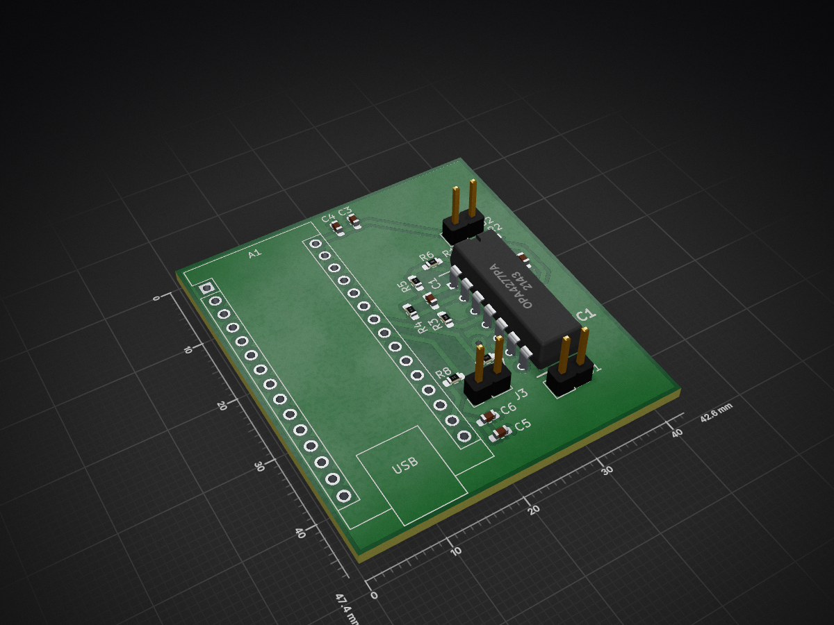
Current sensor is an open-source printed circuit board by pointertoaperson, from the pointertoaperson/current_sensor repository on GitHub. It is a 2-layer board of 42.6 × 47.4 mm with 19 parts on 40 nets, routed with 75 tracks and 1 via.
It is built around the OPA4277PA. Its parts include 8 resistors, 6 capacitors, 3 connectors and 1 IC. It belongs with the sensors and measurement boards and the AVR (ATmega, ATtiny) boards of this library.
read full report
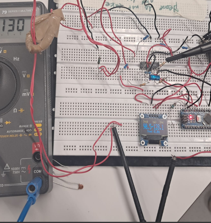
This project implements a non-invasive current measurement system based on a Rogowski coil, combined with embedded digital signal processing and wireless data transmission. The system measures peak current, RMS current, and frequency of an AC signal and publishes the results to an MQTT broker for real-time edge visualization.
The project demonstrates a complete cyber-physical system (CPS) pipeline, spanning analog sensing, bare-metal firmware, digital signal processing, wireless communication, and edge-side visualization.
Rogowski Coil + Signal Conditioning
Produces a small voltage proportional to di/dt, followed by amplification and conditioning.
ATmega328P (16 MHz)
Performs ADC sampling, FIR filtering, digital integration, current calculation, frequency estimation, and display control.
SSD1306 OLED (128×32, I²C)
Displays peak current, RMS current, and frequency locally.
ESP8266
Acts as an SPI slave, connects to Wi-Fi, and publishes data via MQTT.
Edge Device (PC)
Subscribes to MQTT data and visualizes it in real time using Python.
Source files:
main.c – System initialization and main loopadc.c / adc.h – ADC configuration and samplingtimer.c / timer.h – Timer-based sampling controlfir.c / fir.h – FIR filter implementationspi.c / spi.h – SPI communication with ESP8266i2c.c / i2c.h – I²C driverssd1306.c / ssd1306.h – OLED driver| Qty | Value | Footprint | References |
|---|---|---|---|
| 6 | 10k | Resistor_SMD:R_0603_1608Metric_Pad0.98x0.95mm_HandSolder | R1, R2, R3, R5, R7, R8 |
| 3 | Conn_01x02 | Connector_PinHeader_2.54mm:PinHeader_1x02_P2.54mm_Vertical | J1, J2, J3 |
| 2 | 0,1uF | Capacitor_SMD:C_0603_1608Metric_Pad1.08x0.95mm_HandSolder | C3, C5 |
| 2 | 180p | Capacitor_SMD:C_0603_1608Metric_Pad1.08x0.95mm_HandSolder | C1, C2 |
| 2 | 33uF | Capacitor_SMD:C_0603_1608Metric_Pad1.08x0.95mm_HandSolder | C4, C6 |
| 1 | 100k | Resistor_SMD:R_0603_1608Metric_Pad0.98x0.95mm_HandSolder | R6 |
| 1 | 10M | Resistor_SMD:R_0603_1608Metric_Pad0.98x0.95mm_HandSolder | R4 |
| 1 | Arduino_Nano_Every | Module:Arduino_Nano | A1 |
| 1 | OPA4277PA | SamacSys_Parts:DIP794W53P254L1930H508Q14N | IC1 |
It measures 42.6 × 47.4 mm and has 2 copper layers, 1.6 mm thick.
19 parts, built around the OPA4277PA. The full list of its parts is on this page, with links to each part's symbol and footprint where PCBKit's library has them.
From the pointertoaperson/current_sensor repository on GitHub, at the commit this page was made from: the board is kicad schematic and pcb layout/current_sensor.kicad_pcb and its schematic kicad schematic and pcb layout/current_sensor.kicad_sch. PCBKit opens the board in the browser, with nothing to install.
Its repository states no licence, so its author keeps all rights: ask pointertoaperson before reusing the design.

hackclub/OnBoard
💡 Join 1,000 teenagers and make your first PCB with a $100 grant!

polpo/picogus
Emulation of ISA sound cards and CD-ROM on Raspberry Pi Pico (GUS, SB/Adlib, MPU-401, Tandy, CMS, Panasonic CD-ROM) with USB mouse/joystick support


nkitanov/iaq_board
IAQ Board is a DIY (Do-It-Yourself) device for measuring internal air quality


Ardumower/ardumower
Develop an open source robotic lawn mower (HW+SW reference platform)

zmaker/arduino_cookbook
gli sketch del nuovo progetto Arduino Cookbook e dei video di YouTube