2 layers67.9 × 92.1 mm
SensorPod Board
plb500/AutoBloomer-SensorModules
Code and PCB designs for AutoBloomer MQTT sensor modules
21 parts
 plb500/AutoBloomer-SensorModules
Code and PCB designs for AutoBloomer MQTT sensor modules
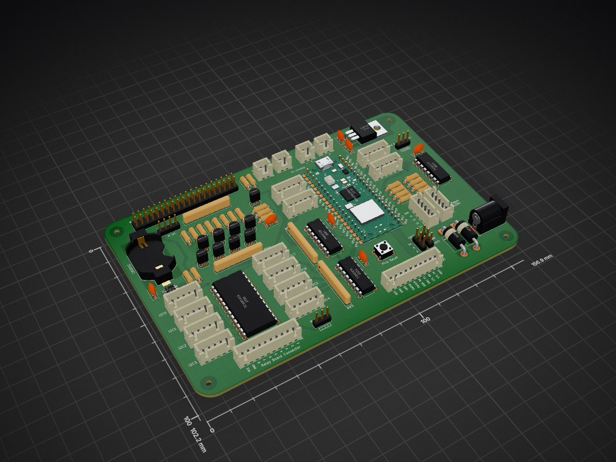
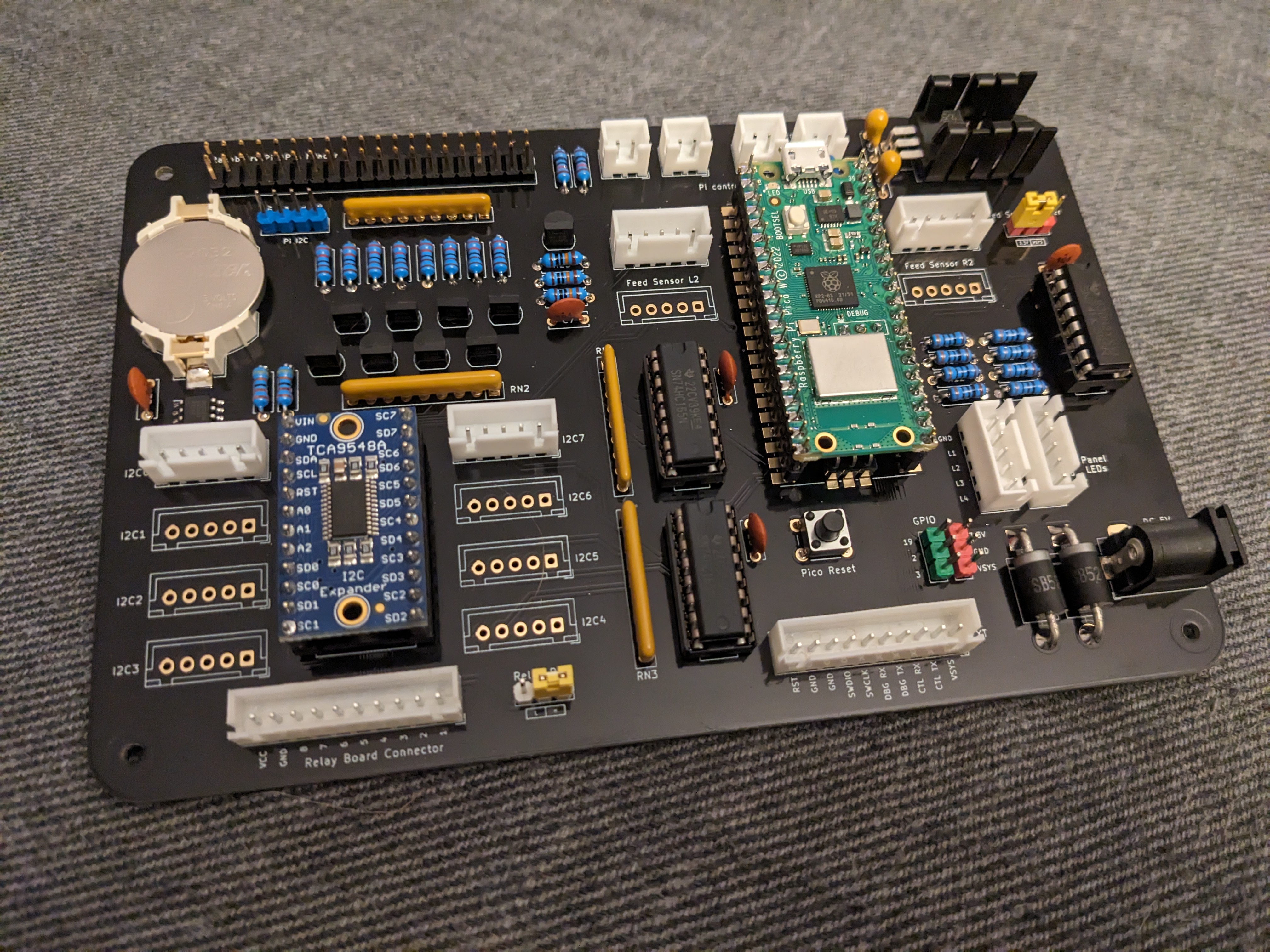
HardwareInterfaceBoard is an open-source printed circuit board by plb500, from the plb500/AutoBloomer-SensorModules repository on GitHub. It is a 2-layer board of 156.9 × 102.2 mm with 85 parts on 147 nets, routed with 859 tracks and 15 vias.
It is built around the TCA9548APW, 74HC165D and 74HC595, with the DS3231MZ/V+, LM1117-3.3 and PN2222A among its other parts. Its parts include 25 connectors, 23 resistors, 9 transistors, 7 capacitors and 7 ICs. It belongs with the home automation and IoT and sensors and measurement boards and the RP2040 boards of this library.


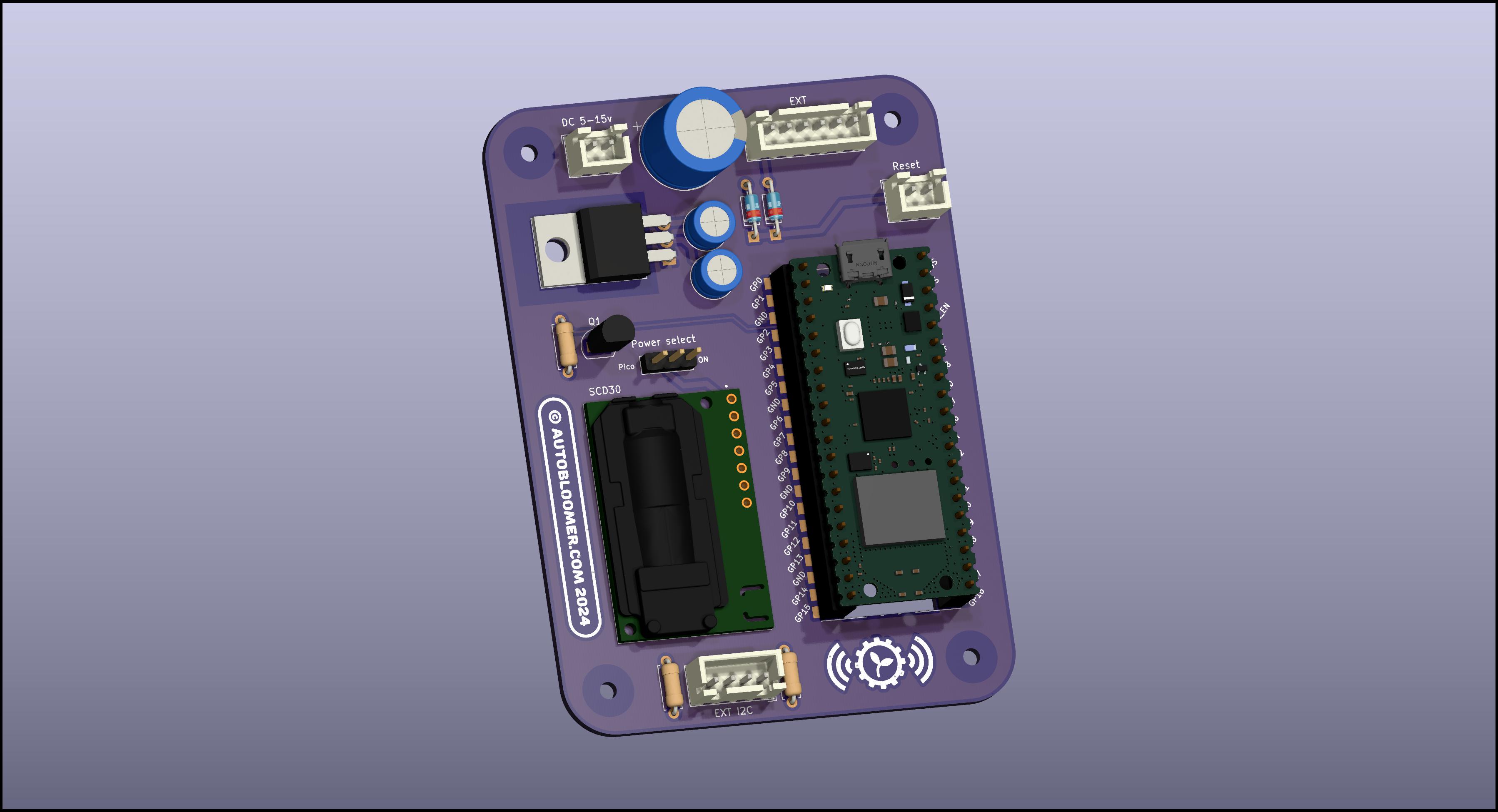
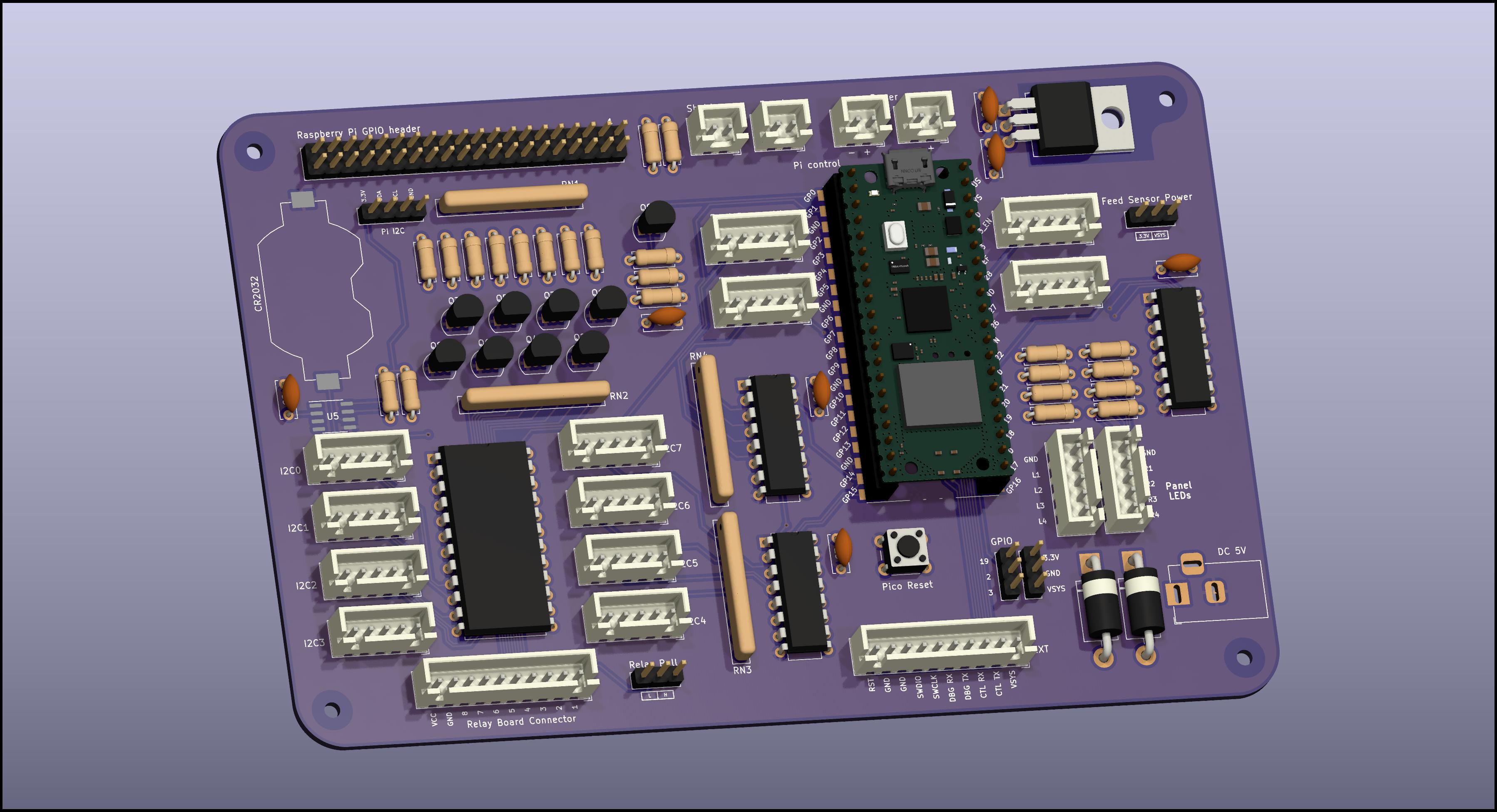
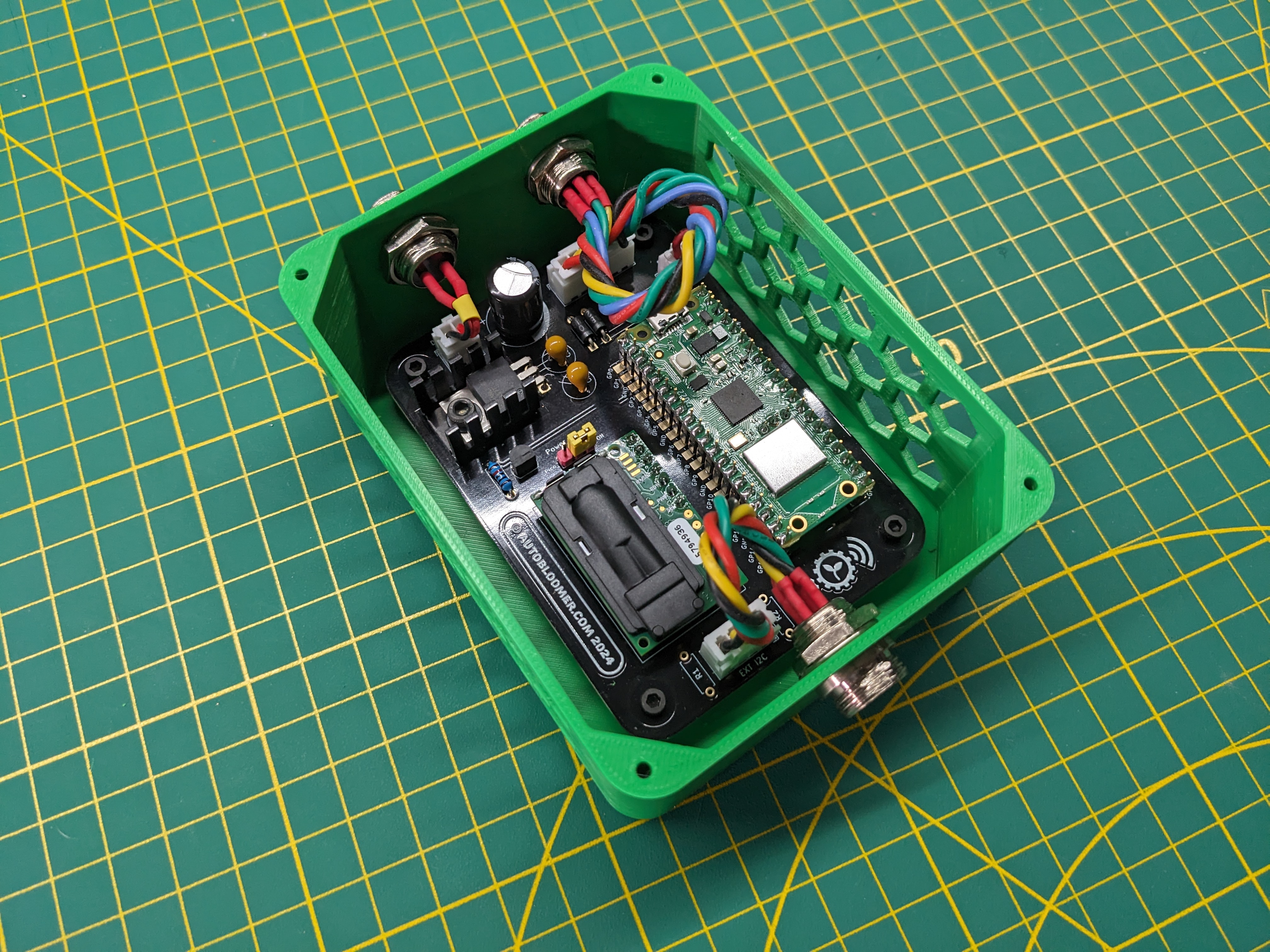
Full plans and code for a sensor controller capable of publishing multiple sensor data via MQTT
Raspberry Pico source code is here
PCB schematics (KiCad format), plans plus any 3D prints/CNC files for the different hardware platforms are here
A brief overview is on YouTube
Under the hood the sensor modules use Raspberry Pico Ws to communicate with an MQTT broker and transmit data it collates from the following sensors:
I also intend to add EC and/or pH sensors to this to essentially make this a one-stop hydroponics sensor interface.
The module arranges these sensors into sensor "groups", referred to by their index. Each group effectively publishes a set of data from multiple sensors to a single MQTT topic. This allows the Sensor Pod, for example, to accumulate sensor data from both the SCD30 sensor and the Stemma Soil Sensor into a single topic, and also allows the HIB to publish sensor data to multiple topics (i.e. the RTC battery voltage and each individual connected feed sensor all publish to their own individual topics)
Currently there are two different hardware platforms defined:
The Sensor Pod consists of a single sensor group providing data from the following sensors:
The HIB consists of two distinct pieces of hardware. One section provides power and hardware control to the Raspberry Pi powering the AutoBloomer controller, along with a RTC module and interfacing to relays. The other section is the sensor module which provides data from feed level sensors along with the current RTC battery module voltage. These are grouped as follows:
Configuration of each module is done in two ways:
Basic pod configuration of essential runtime variables (wireless SSID/key, broker address, module location/name etc) is done via serial port connected to the bord's EXT header (3.3v, 57600/8/n/1) and transmitting commands in the format: <COMMAND><SENSOR_GROUP><PARAMETER> (note no space)
SSIDMyNetwork -> Sets the sensor module to connect to the wireless network with the SSID "MyNetwork"PASSthe_key -> Sets the sensor module to connect to the wireless network using the PSK "the_key"NAMESensorModule -> Sets the Pico's host/MQTT client name to be "SensorModule"BRKRthebroker.local -> Tells the sensor module to connect and publish to the MQTT broker with host name "thebroker.local"BRKR192.168.1.50 -> Tells the sensor module to connect and publish to the MQTT broker at address "192.168.1.50"GRPN0Group1Sensor -> Sets the name of the sensor group at index 0 to "Group1Sensor"GRPL0LeftChamber -> Sets the location of the sensor group at index 0 to "LeftChamber"Once these have been set the pod will attempt to connect to the configured broker via the supplied wireless network and begin publishing sensor data to the topic:
AutoBloomer/<< sensor group location >>/<< sensor group name >>Once connected, the pod will also subscribe to a specific MQTT topic to listen for sensor calibration commands. The topic in question is:
AutoBloomer/<< sensor group location >>/<< sensor group name >>/controlThe payload consists of a single line detailing the type of calibration to be performed. Currently the only sensor capable of (and requiring) calibration is the SCD30 on the Sensor Pod. Calibration commands are one of the following:
For example, setting a FRC value of 400 (i.e. recalibrating outside) and using mosquitto_pub the command line would look something like this:
mosquitto_pub -h broker.address -m "FRC 400" -t "AutoBloomer/SensorLocation/SensorName/control"For more details on these parameters, see the SCD30 documentation here
| Qty | Value | Footprint | References |
|---|---|---|---|
| 8 | 2.2k | Resistor_THT:R_Axial_DIN0207_L6.3mm_D2.5mm_P7.62mm_Horizontal | R1, R2, R3, R4, R5, R6, R7, R8 |
| 8 | 300 | Resistor_THT:R_Axial_DIN0207_L6.3mm_D2.5mm_P7.62mm_Horizontal | R11, R12, R13, R14, R15, R16, R17, R18 |
| 8 | PN2222A | Package_TO_SOT_THT:TO-92_Inline | Q1, Q2, Q3, Q4, Q5, Q6, Q7, Q8 |
| 5 | 0.1uf | Capacitor_THT:C_Disc_D6.0mm_W2.5mm_P5.00mm | C1, C2, C3, C6, C7 |
| 4 | 10k | Resistor_THT:R_Array_SIP9 | RN1, RN2, RN3, RN4 |
| 4 | MountingHole_2.5mm | MountingHole:MountingHole_2.5mm | H1, H2, H3, H4 |
| 3 | 100k | Resistor_THT:R_Axial_DIN0207_L6.3mm_D2.5mm_P7.62mm_Horizontal | R21, R22, R23 |
| 2 | 10k | Resistor_THT:R_Axial_DIN0207_L6.3mm_D2.5mm_P7.62mm_Horizontal | R9, R10 |
| 2 | 10uf | Capacitor_THT:C_Disc_D6.0mm_W2.5mm_P5.00mm | C4, C5 |
| 2 | 4.3k | Resistor_THT:R_Axial_DIN0207_L6.3mm_D2.5mm_P7.62mm_Horizontal | R19, R20 |
| 2 | 74HC165 | Package_DIP:DIP-16_W7.62mm | U6, U7 |
| 2 | SB520 | Diode_THT:D_DO-201AD_P15.24mm_Horizontal | D1, D2 |
| 1 | 74HC595 | Package_DIP:DIP-16_W7.62mm | U2 |
| 1 | CR2032 | Battery:BatteryHolder_Keystone_1058_1x2032 | BT1 |
| 1 | DC 5V | Connector_BarrelJack:BarrelJack_Horizontal_MP | J4 |
| 1 | DS3231MZ | Package_SO:SOIC-8_3.9x4.9mm_P1.27mm | U5 |
| 1 | Display 5V | Connector_JST:JST_XH_B2B-XH-A_1x02_P2.50mm_Vertical | J3 |
| 1 | EXT | Connector_JST:JST_XH_B10B-XH-A_1x10_P2.50mm_Vertical | J20 |
| 1 | Feed Sensor L1 | Connector_JST:JST_XH_B5B-XH-A_1x05_P2.50mm_Vertical | J6 |
| 1 | Feed Sensor L2 | Connector_JST:JST_XH_B5B-XH-A_1x05_P2.50mm_Vertical | J9 |
| 1 | Feed Sensor Power | Connector_PinHeader_2.54mm:PinHeader_1x03_P2.54mm_Vertical | JP2 |
| 1 | Feed Sensor R1 | Connector_JST:JST_XH_B5B-XH-A_1x05_P2.50mm_Vertical | J8 |
| 1 | Feed Sensor R2 | Connector_JST:JST_XH_B5B-XH-A_1x05_P2.50mm_Vertical | J11 |
| 1 | GPIO | Connector_PinHeader_2.54mm:PinHeader_1x03_P2.54mm_Vertical | J5 |
| 1 | I2C0 | Connector_JST:JST_XH_B5B-XH-A_1x05_P2.50mm_Vertical | J26 |
| 1 | I2C1 | Connector_JST:JST_XH_B5B-XH-A_1x05_P2.50mm_Vertical | J27 |
| 1 | I2C2 | Connector_JST:JST_XH_B5B-XH-A_1x05_P2.50mm_Vertical | J28 |
| 1 | I2C3 | Connector_JST:JST_XH_B5B-XH-A_1x05_P2.50mm_Vertical | J29 |
| 1 | I2C4 | Connector_JST:JST_XH_B5B-XH-A_1x05_P2.50mm_Vertical | J30 |
| 1 | I2C5 | Connector_JST:JST_XH_B5B-XH-A_1x05_P2.50mm_Vertical | J31 |
| 1 | I2C6 | Connector_JST:JST_XH_B5B-XH-A_1x05_P2.50mm_Vertical | J32 |
| 1 | I2C7 | Connector_JST:JST_XH_B5B-XH-A_1x05_P2.50mm_Vertical | J33 |
| 1 | LM1117 | Package_TO_SOT_THT:TO-220-3_Horizontal_TabDown | U4 |
| 1 | Left LEDs | Connector_JST:JST_XH_B5B-XH-A_1x05_P2.50mm_Vertical | J14 |
| 1 | Pi 5V | Connector_JST:JST_XH_B2B-XH-A_1x02_P2.50mm_Vertical | J2 |
| 1 | Pico Reset | Button_Switch_THT:SW_PUSH_6mm | SW1 |
| 1 | Power bus | Connector_PinHeader_2.54mm:PinHeader_1x03_P2.54mm_Vertical | J7 |
| 1 | RTC Header | Connector_PinHeader_2.54mm:PinHeader_1x04_P2.54mm_Vertical | J25 |
| 1 | Raspberry Pi GPIO header | Connector_PinHeader_2.54mm:PinHeader_2x20_P2.54mm_Vertical | J24 |
| 1 | Raspberry Pico | RPi_Pico:RPi_PicoW_SMD_TH | U1 |
| 1 | Relay Board Connector | Connector_JST:JST_XH_B10B-XH-A_1x10_P2.50mm_Vertical | J1 |
| 1 | Relay Pull | Connector_PinHeader_2.54mm:PinHeader_1x03_P2.54mm_Vertical | JP1 |
| 1 | Reset | Connector_JST:JST_XH_B2B-XH-A_1x02_P2.50mm_Vertical | J16 |
| 1 | Right LEDs | Connector_JST:JST_XH_B5B-XH-A_1x05_P2.50mm_Vertical | J15 |
| 1 | Shutdown | Connector_JST:JST_XH_B2B-XH-A_1x02_P2.50mm_Vertical | J17 |
| 1 | TCA9548A | Package_DIP:DIP-24_W15.24mm | U3 |
| 1 | TP0610L | Package_TO_SOT_THT:TO-92_Inline | Q9 |
plb500/AutoBloomer-SensorModules
Code and PCB designs for AutoBloomer MQTT sensor modules


westlicht/performer-hardware
PER|FORMER Eurorack Sequencer - Hardware Design Files


laenzlinger/granit
Custom carrier board for Raspberry Pi CM4/CM5 — minimal offsite backup appliance with JMS578 USB-to-SATA bridge


lhm0/talking_clock
A talking clock for visually impaired users. ESP32 controlled, fully offline, long battery life.

It measures 156.9 × 102.2 mm and has 2 copper layers, 1.6 mm thick.
85 parts, built around the TCA9548APW, 74HC165D, 74HC595 and DS3231MZ/V+. The full list of its parts is on this page, with links to each part's symbol and footprint where PCBKit's library has them.
From the plb500/AutoBloomer-SensorModules repository on GitHub, at the commit this page was made from: the board is hardware/HIB/PCB/HardwareInterfaceBoard.kicad_pcb and its schematic hardware/HIB/PCB/HardwareInterfaceBoard.kicad_sch. PCBKit opens the board in the browser, with nothing to install.
Its repository states no licence, so its author keeps all rights: ask plb500 before reusing the design.