
2 layers144.3 × 22.4 mm
Touchboard
plan44/pixelboard-hardware
Pixelboard game lounge table - hardware (laser cut plans, schematics, PCBs)
27 parts4

 plan44/pixelboard-hardware4
Pixelboard game lounge table - hardware (laser cut plans, schematics, PCBs)
Controlboard is an open-source printed circuit board by plan44, from the plan44/pixelboard-hardware repository on GitHub. It is a 2-layer board of 61.5 × 46.5 mm with 37 parts on 33 nets, routed with 534 tracks and 40 vias.
It is built around the 74AHCT1G125SE. Its parts include 13 capacitors, 9 resistors, 7 connectors and 4 ICs.
The Pixelboard is a 80*40cm lounge table board only 24mm thick, integrating a 10x20 color pixel matrix, 8 touch keys, a linux controller with WiFi and ethernet and even a power supply. All disguised under a dark plexiglass, looking like a regular lounge table until touched...
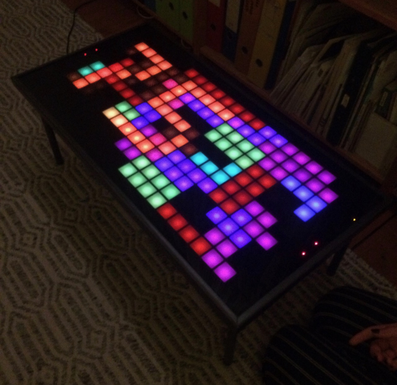
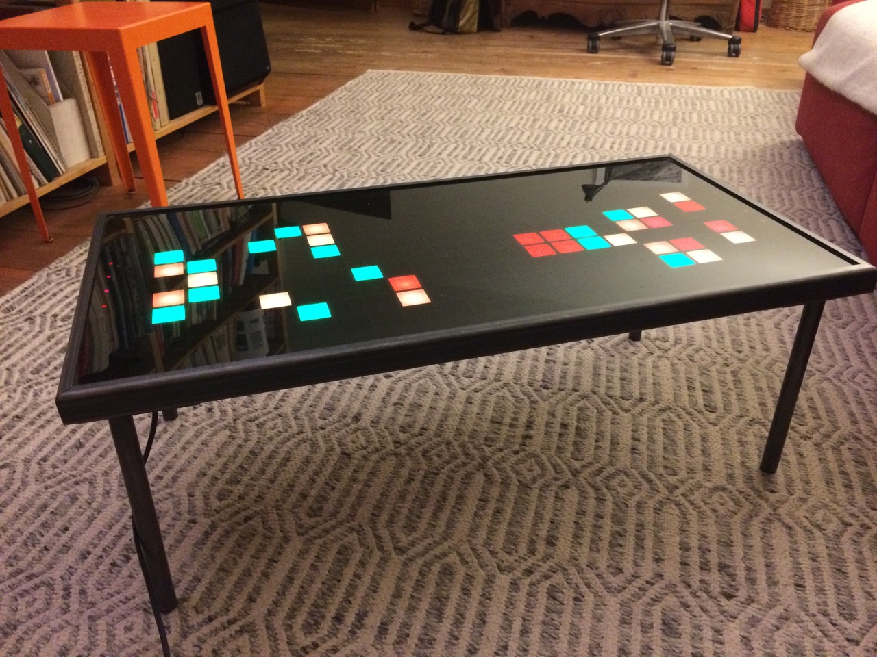
With the current software (see pixelboardd and pixelboard-config in plan44-feed) you can play tetris (alone or 2 players each on one end of the board), watch Conway's game of life, let text messages scroll over the surface and display small 10x20 pixel PNG images (via web interface).
The board itself is made of 5 layers of lasered plywood and plexiglass. The construction plan is a Affinity Designer drawing in mechanics/ and there are SVG exports of the layers in mechanics/exported SVGs for laser/.
The pixels are made of 33mm spaced WS2813 LED strips, arranged in a 10*20 matrix, all power and data lines connected by two narrow PCBs (see KiCAD files in electronics/connectorboard, PCBs can be ordered here). The board is designed such that it works for both sides of the matrix (flipped over at the far end).
The control board is built around a Onion Omega2, a MediaTek MT7688 based MIPS board with built-in WiFi, 64MB RAM and 16MB Flash, running a LEDE/OpenWRT Linux based firmware (see here for how to build the firmware from scratch). The KiCAD files are in electronics/controlboard, PCBs can be ordered here).
The two identical touch key boards are based on the AT42QT1070 chip for handling the touch detection plus a i2c port extender for connecting the indicator LEDs placed in the middle under each touch key. The KiCAD files are in electronics/touchboard, PCBs can be ordered here).
And in photos there are a few images showing various states of assembling all this:
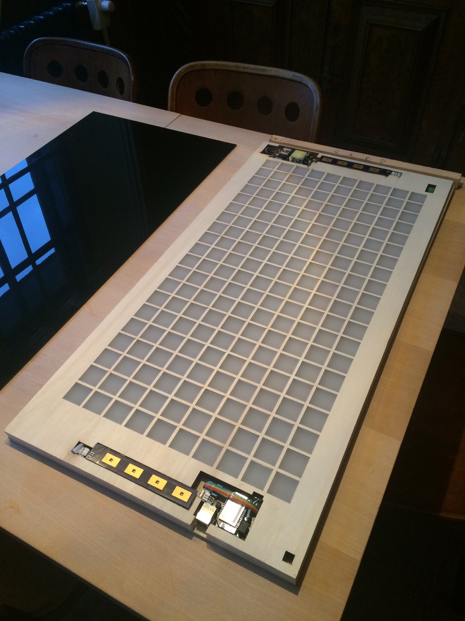 Front glass removed
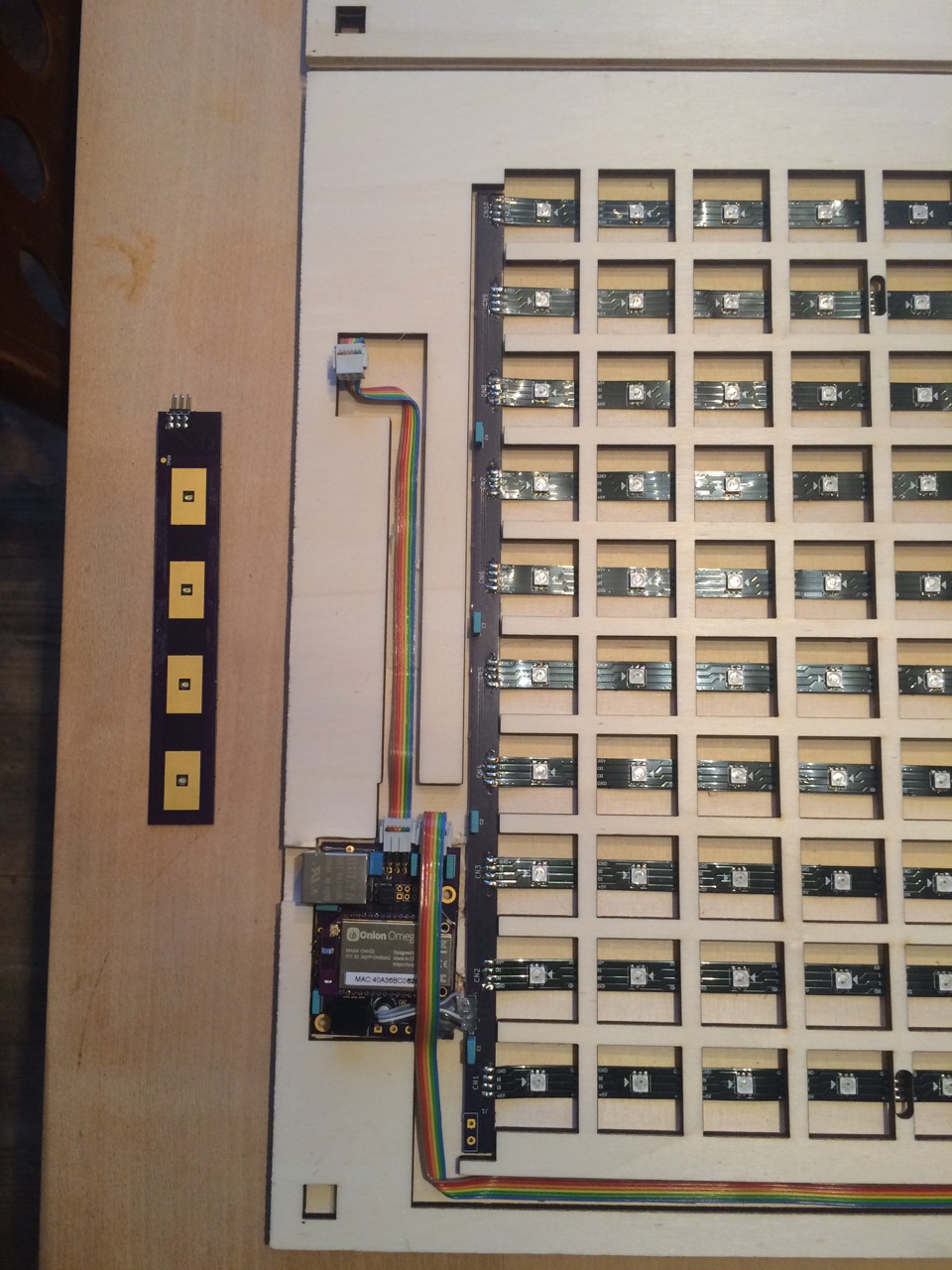 Controlboard side, just base plate and first lasered frame (lower carrier) keeping the LED matrix, cables, and controlboard in place.
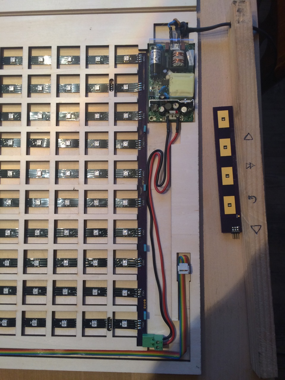 Power supply side, base plate and lower carrier.
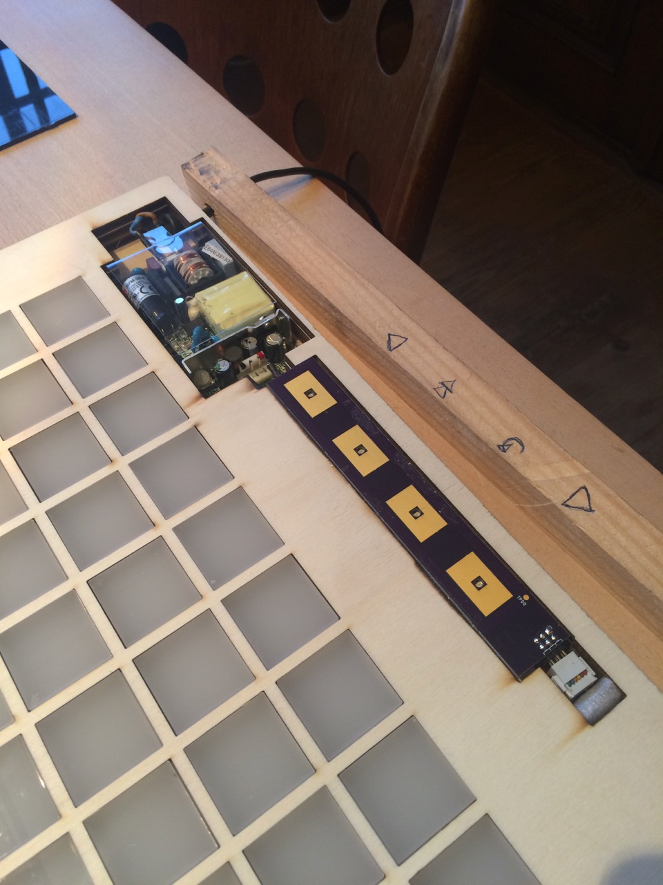 Power supply side, now with all plywood layers and touchboard mounted.
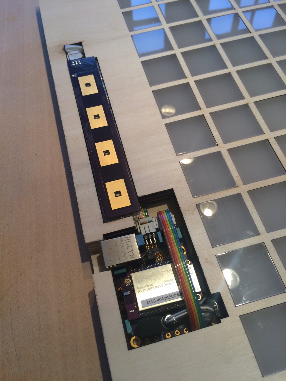 Controlboard side, all plywood layers mounted, diffusor plexi sqares inserted, touchboard mounted. Note that this photo does not yet show the hole for a little speaker connected to the MAX98357A i2s amp (but the plan drawings have it).
| Qty | Value | Footprint | References |
|---|---|---|---|
| 7 | 100nF | Capacitors_SMD:C_1206_HandSoldering | C1, C2, C3, C5, C6, C7, C11 |
| 4 | 49.9_1% | Resistors_SMD:R_0805_HandSoldering | R1, R2, R3, R4 |
| 2 | 100k | Resistors_SMD:R_1206_HandSoldering | R7, R8 |
| 2 | 1M | Resistors_SMD:R_1206_HandSoldering | R6, R9 |
| 2 | 220pF | Capacitors_SMD:C_1206_HandSoldering | C12, C13 |
| 2 | CONN_01X01 | Mounting_Holes:MountingHole_3.2mm_M3_DIN965_Pad | MH1, MH2 |
| 2 | CONN_02X03 | Pin_Headers:Pin_Header_Angled_2x03_Pitch2.54mm | P3, P4 |
| 2 | Ferritebead | Capacitors_SMD:C_1206_HandSoldering | FB1, FB2 |
| 1 | 10uF | Capacitors_SMD:C_1206_HandSoldering | C10 |
| 1 | 10uF | Capacitors_ThroughHole:CP_Radial_D6.3mm_P2.50mm | C4 |
| 1 | 1k | Resistors_SMD:R_1206_HandSoldering | R5 |
| 1 | 1uF | Capacitors_SMD:C_1206_HandSoldering | C8 |
| 1 | 33uF | Capacitors_ThroughHole:CP_Radial_D6.3mm_P2.50mm | C9 |
| 1 | 74AHCT1G125 | TO_SOT_Packages_SMD:SOT-353 | U5 |
| 1 | CONN_01X02 | Pin_Headers:Pin_Header_Angled_1x02_Pitch2.54mm | P5 |
| 1 | CONN_01X04 | Pin_Headers:Pin_Header_Straight_1x04_Pitch2.54mm | P1 |
| 1 | CONN_02X02 | Pin_Headers:Pin_Header_Straight_2x02_Pitch2.54mm | P7 |
| 1 | FDI_Cable | Pin_Headers:Pin_Header_Straight_1x06_Pitch2.54mm | P2 |
| 1 | HLJ-6115ANL | plan44:plan44-HLJ-6115ANL | J3 |
| 1 | MAX98357A | Housings_DFN_QFN:QFN-16-1EP_3x3mm_Pitch0.5mm | U3 |
| 1 | ONION-OMEGA2 | plan44:plan44-ONION-2MM-2X16 | U1 |
| 1 | Recom_R78Cxx | plan44-Recom-R78Cxx | U2 |
plan44/pixelboard-hardware
Pixelboard game lounge table - hardware (laser cut plans, schematics, PCBs)

plan44/pixelboard-hardware
Pixelboard game lounge table - hardware (laser cut plans, schematics, PCBs)


wntrblm/Big_Honking_Button
A simple Eurorack sampler and performance module in a silly package.

arturo182/keyboard_featherwing_hw
The Keyboard FeatherWing is an easy way to add a handheld Qwerty keyboard and a 2.6” color display (+ more) to your project! It fits well in your hands and is great for typing with your thumbs, early 2000s-style.

realworldpixel/home-assistant-keypad
A 9-key macro keypad for Home Assistant, running ESPHome. Every key is RGB backlit, and comes in two variants: one that sits on a desk and one that mounts on a wall, with magnets or screws.

romix123/P1-wifi-gateway
Deze software brengt verschillende componenten bij elkaar in een handzaam pakket.


It measures 61.5 × 46.5 mm and has 2 copper layers, 1.6 mm thick.
37 parts, built around the 74AHCT1G125SE. The full list of its parts is on this page, with links to each part's symbol and footprint where PCBKit's library has them.
From the plan44/pixelboard-hardware repository on GitHub, at the commit this page was made from: the board is electronics/controlboard/controlboard.kicad_pcb. PCBKit opens the board in the browser, with nothing to install.
Its repository states no licence, so its author keeps all rights: ask plan44 before reusing the design.