2 layers50 × 50 mm
Open Battery Charger
DavidVeloz95/Open-Source-Battery-Smart-Charger
Embedded power electronics project: intelligent 2S Li-Ion charger with protection, power switching and monitoring, designed in KiCad.
47 partsMIT

 pkwill01/lo-cate
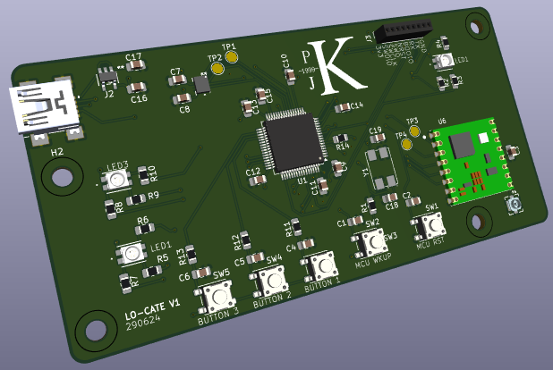
Lo cate pcb is an open-source printed circuit board by pkwill01, from the pkwill01/lo-cate repository on GitHub. It is a 4-layer board of 100 × 50 mm with 58 parts on 83 nets, routed with 398 tracks and 73 vias.
It is built around the BMI323, LDK320AM33R and RFM95W-868S2. Its parts include 19 capacitors, 14 resistors, 8 ICs, 5 switches and 2 connectors. It belongs with the STM32 boards of this library.


A PCB and firmware project to create a simple LoRa capable device with an intergrated IMU.
The PCB was designed to be simple, power over USB and be manufactorable using basic electrical tooling.
| Qty | Value | Footprint | References |
|---|---|---|---|
| 15 | 0.1uF | Capacitor_SMD:C_0805_2012Metric_Pad1.18x1.45mm_HandSolder | C1, C2, C3, C4, C5, C6, C7, C8, C9, C10, C11, C12, C13, C14, C16 |
| 9 | 60Ω | Resistor_SMD:R_0805_2012Metric_Pad1.20x1.40mm_HandSolder | R2, R3, R4, R5, R6, R7, R8, R9, R10 |
| 4 | MountingHole | MountingHole:MountingHole_3.2mm_M3 | H1, H2, H3, H4 |
| 3 | 50k | Resistor_SMD:R_0805_2012Metric_Pad1.20x1.40mm_HandSolder | R11, R12, R13 |
| 2 | 10p | Capacitor_SMD:C_0805_2012Metric_Pad1.18x1.45mm_HandSolder | C18, C19 |
| 1 | 0.47uF | Capacitor_SMD:C_0805_2012Metric_Pad1.18x1.45mm_HandSolder | C17 |
| 1 | 10k | Resistor_SMD:R_0805_2012Metric_Pad1.20x1.40mm_HandSolder | R1 |
| 1 | 30R | Resistor_SMD:R_0805_2012Metric_Pad1.20x1.40mm_HandSolder | R14 |
| 1 | 4.7uF | Capacitor_SMD:C_0805_2012Metric_Pad1.18x1.45mm_HandSolder | C15 |
| 1 | 690-005-299-043 | footprints:EDAC_690-005-299-043 | J2 |
| 1 | 734120114 | footprints:73412-0114_MOL | U8 |
| 1 | BMI323 | footprints:BMI323_BOS-M | U2 |
| 1 | BUTTON1 | Button_Switch_SMD:SW_SPST_PTS647_Sx38 | SW3 |
| 1 | BUTTON2 | Button_Switch_SMD:SW_SPST_PTS647_Sx38 | SW4 |
| 1 | BUTTON3 | Button_Switch_SMD:SW_SPST_PTS647_Sx38 | SW5 |
| 1 | Conn_01x09_Pin | Connector_PinSocket_1.27mm:PinSocket_1x09_P1.27mm_Vertical | J3 |
| 1 | Crystal_GND24_Small | Crystal:Crystal_SMD_7050-4Pin_7.0x5.0mm | Y1 |
| 1 | LDK320AM33R | footprints:SOT23-5L_STM-M | U7 |
| 1 | LED1 | footprints:150141M173100_WRE-M | U3 |
| 1 | LED2 | footprints:150141M173100_WRE-M | U4 |
| 1 | LED3 | footprints:150141M173100_WRE-M | U5 |
| 1 | LOGO | footprints:Logo_CADPAD_2 | G*** |
| 1 | MICRO_ON | Button_Switch_SMD:SW_SPST_PTS647_Sx38 | SW2 |
| 1 | MICRO_RESET | Button_Switch_SMD:SW_SPST_PTS647_Sx38 | SW1 |
| 1 | RFM95W-868S2 | footprints:XCVR_RFM95W-868S2 | U6 |
| 1 | STM32F401RETx | Package_QFP:LQFP-64_10x10mm_P0.5mm | U1 |
| 1 | TP_IMU_MISO | TestPoint:TestPoint_Pad_D2.0mm | TP1 |
| 1 | TP_IMU_MOSI | TestPoint:TestPoint_Pad_D2.0mm | TP2 |
| 1 | TP_LORA_MISO | TestPoint:TestPoint_Pad_D2.0mm | TP3 |
| 1 | TP_LORA_MOSI | TestPoint:TestPoint_Pad_D2.0mm | TP4 |
It measures 100 × 50 mm and has 4 copper layers, 1.6 mm thick.
58 parts, built around the BMI323, LDK320AM33R and RFM95W-868S2. The full list of its parts is on this page, with links to each part's symbol and footprint where PCBKit's library has them.
From the pkwill01/lo-cate repository on GitHub, at the commit this page was made from: the board is pcb/lo_cate_pcb/lo_cate_pcb.kicad_pcb and its schematic pcb/lo_cate_pcb/lo_cate_pcb.kicad_sch. PCBKit opens the board in the browser, with nothing to install.
Its repository states no licence, so its author keeps all rights: ask pkwill01 before reusing the design.
DavidVeloz95/Open-Source-Battery-Smart-Charger
Embedded power electronics project: intelligent 2S Li-Ion charger with protection, power switching and monitoring, designed in KiCad.

SunDevilRocketry/Flight-Computer
General purpose flight computer for high powered rocketry projects.


crsknr/hw_udsp-card
A compact DSP development board for real-time embedded audio and sensing

hongtannnn/amr_stm32
AMR Hardware & PCB Design: Low-level controller board and hardware system (STM32 / KiCad) engineered as the foundation for future ROS 2, SLAM, and autonomous navigation integration.


Protocentral/protocentral_healthypi6_hardware
Open hardware design files for HealthyPi 6 — STM32H757 vital-signs monitor with the HealthyLink modular expansion bus