
4 layers112.7 × 67.8 mm

BelayBox reference hardware
Yeti is an open-source printed circuit board by PionixPublic, from the PionixPublic/reference-hardware repository on GitHub, published under the CERN-OHL-P-2.0 licence. It is an 8-layer board of 163.5 × 123.5 mm with 278 parts on 210 nets, routed with 2,762 tracks and 718 vias.
It is built around the STM32G431RBT6, CAM-M8Q-0 and AHES4291, with the MPM-30-12, MYRGC075050S31RA and RS485 among its other parts. Its parts include 97 capacitors, 88 resistors, 19 diodes, 18 ICs and 12 connectors. It belongs with the STM32 boards of this library.


This repository contains two reference board designs meant to get started with EVerest with a fully working hardware and software solution, entirely open source. They are meant to be developer friendly, not mass production friendly, keep that in mind when using this as a start to design a product. They are designed with KiCAD 6 (https://www.kicad.org/), make sure you use the latest version of KiCAD.
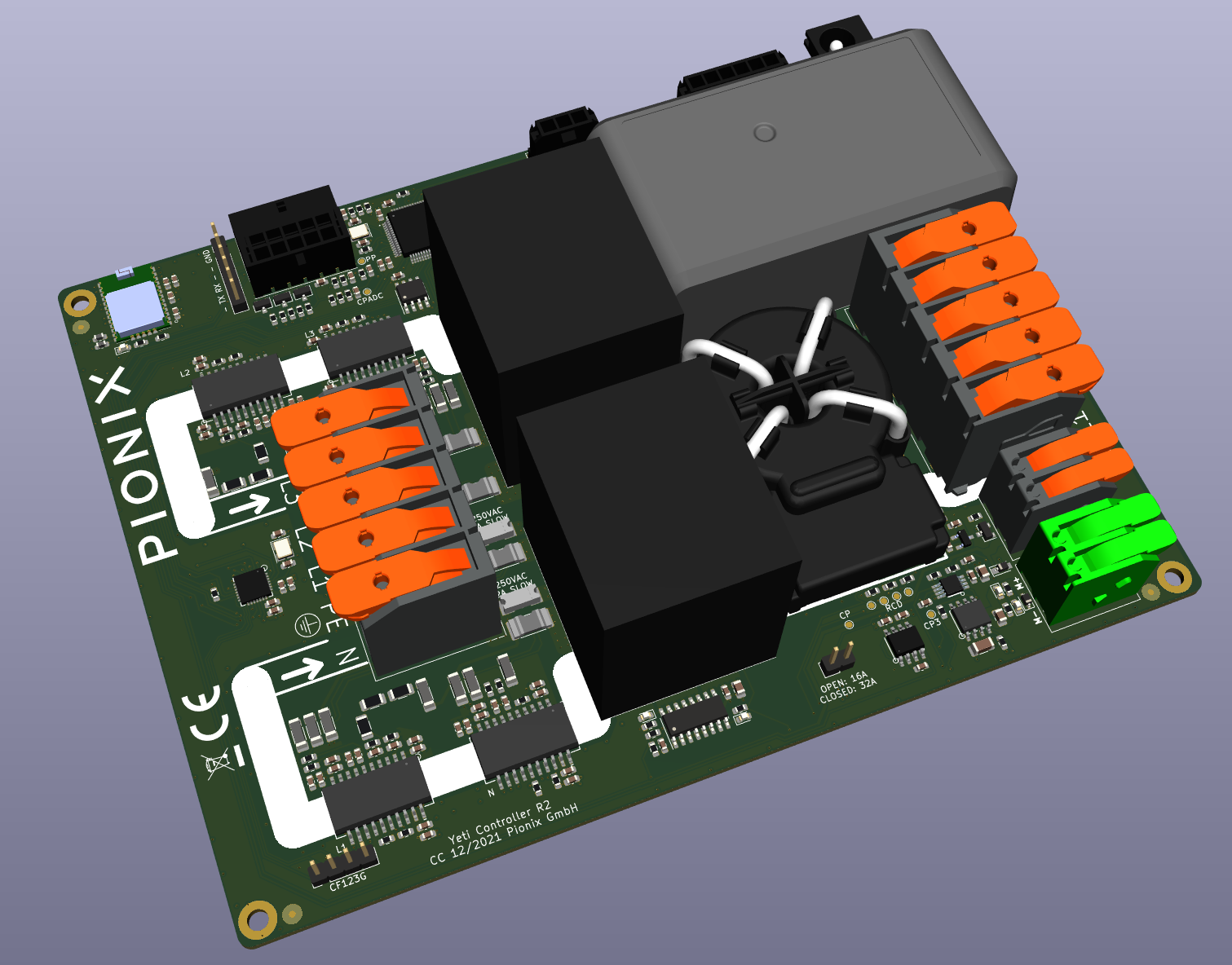
Three phase power board reference design for a full 22kW AC charger. This board may be used in two ways:
By default Yeti is a complete AC charger for electric vehicles supporting IEC-61851-1 / SAE J1772 basic charging. It contains the complete charging logic and will charge the car immediately when connected. The UART can optionally be used to observe the status and have limited control over the charging session (such as pause/resume and current limit adjustments). This mode is called "high level control" mode in the yeti firmware. Typical application would be a simple (non-smart) home charger.
The Yeti firmware can be switched to "low level" control mode with a UART command. In this mode the charging logic must be external, only the very basic state machine for states A-F remains in the microcontroller. This basic state machine is essential for electrical safety as it is the actual decision point for switching power on/off etc.
In high level control mode Yeti an external board sets the PWM dutycycle and reads back the control pilot events. This is the mode used by the open-source EVerest stack to also enable HLC (high level charging, aka ISO15118-2/-20/DIN SPEC70121). Automatic switching back to "high level mode" can be implemented to fall back to emergency free charging in case the higher level linux board fails.
Yeti HW has the following features:
It is designed for 4kV reinforced isolation and corresponding creepages to meet IEC61851-1 electrical safety requirements. The isolation barrier is the big white strip, the high level board is therefore in the low voltage domain with reinforced isolation to the high voltage section. If you build boards your self note the special layer stackup requirements for that.
Yeti's STM32 firmware can be found here: https://github.com/PionixPublic/yeti-firmware

Yak is a high level control board for EV charging stations. It supports both AC and DC applications. It is based on Raspberry Pi Compute Module (CM4) running Linux. It has the following features:
For the EVerest software stack on the Yak board see its main repository here: https://github.com/EVerest/everest
Pre built images for the Yak board based on raspian for Pionix BelayBox are available from Pionix: contact@pionix.de
A word of warning: Working with high voltages (e.g. 400V AC or 1000V DC) is dangerous and potentially lethal. The following setups are for experimental use by trained professionals in controlled lab space only! There is risk of death, fire and more, so don't do this unless you know exactly what you are doing. We don't take any responsibility, these instructions are incomplete and may be wrong, you have been warned!
Yeti was designed for AC charging, so wiring for AC is quite easy. You can use both single and three phase configurations with neutral. If you have 220V in the US with no neutral you can wire L1 to L1 and L2 to N. PE must always be connected.

Yak was designed for both AC and DC applications. Even though Yeti was designed for AC only, it can still be used to evaluate DC charging. Keep in mind that this is a bare minimum lab test setup and for a real product more safety and protection features need to be added.
From the Yeti the CP signalling is used as it is the same for DC and AC. The power relais on the Yeti are used as driver relais for the big DC contactor's coil voltage (typically 12 or 24V). Since no AC is connected to Yeti the onboard 12V power supply does not work and external 12V needs to be fed into the barrel connector to power both Yak and Yeti. PE always has to be connected to the Yeti's PE input!
The complete DC power path is added externally. The AC/DC module (or stack of modules) is controlled by EVerest directly from Yak via CAN bus. Isolation monitors and power meters are typically connected to the ModBus/RS485 port of the Yak. Depending on your setup the components may use different busses.
The Yeti firmware is the same as for AC. In the EVerest configuration EvseManager needs to be configured for DC charging mode and the driver modules for all exteral components need to be loaded.

A complete charger design based on those two boards is available from Pionix. You can download the 3D files via our Fusion360 project: https://a360.co/45erK90.
You can find the manual for the BelayBox here: https://pionix.com/user-manual-belaybox
For assembly instructions and some troubleshooting information, please see here: https://everest.github.io/nightly/hardware/pionix_belay_box.html#pionix-belaybox
If you have already purchased a BelayBox and need hardware-related help, see our support page to create an issue: https://support.pionix.com/
For software-related issues all around EVerest, the active community is willing to help you on the EVerest mailing list (https://lists.lfenergy.org/g/everest) or via Zulip (https://lfenergy.zulipchat.com/).
In case you need further parts for the BelayBox, visit the Pionix online shop: https://shop.pionix.com/

This is how a 30kW lab prototype for DC charging evaluation can look like, contact us via contact@pionix.de to get more information.

| Qty | Value | Footprint | References |
|---|---|---|---|
| 37 | 100n | Capacitor_SMD:C_0603_1608Metric | C1, C4, C13, C14, C15, C20, C23, C24, C25, C30, C35, C36, C37, C42, C47, C48 +21 |
| 27 | 10u | Capacitor_SMD:C_0603_1608Metric | C3, C5, C16, C17, C18, C19, C26, C27, C28, C29, C38, C39, C40, C41, C104, C109 +11 |
| 20 | 10k | Resistor_SMD:R_0603_1608Metric | R17, R29, R35, R44, R45, R49, R50, R59, R60, R69, R114, R129, R130, R131, R132, R134 +4 |
| 18 | 1k | Resistor_SMD:R_0603_1608Metric | R13, R16, R40, R41, R42, R43, R47, R48, R55, R56, R57, R58, R65, R66, R67, R110 +2 |
| 15 | LI1806C151R-10 | Inductor_SMD:L_1806_4516Metric | FB1, FB2, FB3, FB4, FB5, FB6, FB7, FB8, FB9, FB10, FB11, FB12, FB13, FB14, FB15 |
| 14 | 33n/25V | Capacitor_SMD:C_0603_1608Metric | C9, C10, C11, C12, C21, C22, C31, C32, C33, C34, C43, C44, C45, C46 |
| 11 | 220 | Resistor_SMD:R_0603_1608Metric | R2, R3, R4, R5, R6, R7, R8, R9, R10, R11, R12 |
| 9 | 267k/500V | Resistor_SMD:R_1206_3216Metric | R37, R38, R39, R52, R53, R54, R62, R63, R64 |
| 9 | GSOT03C-E3-08 | Package_TO_SOT_SMD:SOT-23 | D2, D3, D4, D5, D6, D7, D8, D9, D16 |
| 6 | 680 | Resistor_SMD:R_0603_1608Metric | R31, R32, R33, R77, R113, R115 |
| 4 | 100k | Resistor_SMD:R_0603_1608Metric | R1, R74, R86, R90 |
| 4 | ADE7932ARIZ | ev-devboard:ADE7933ARIZ | U11, U12, U13, U14 |
| 4 | Fiducial | Fiducial:Fiducial_1mm_Mask3mm | FID1, FID2, FID3, FID4 |
| 4 | LED GREEN | LED_SMD:LED_0603_1608Metric | D10, D11, D15, D36 |
| 4 | MountingHole | MountingHole:MountingHole_3.2mm_M3_ISO7380_Pad_TopBottom | H1, H2, H3, H4 |
| 4 | WSLF2512L5000FEA | ev-devboard:WSLF2512L5000FEA | R36, R46, R51, R61 |
| 3 | 10u 25V | Capacitor_SMD:C_0603_1608Metric | C63, C110, C111 |
| 3 | 10u_50V | Capacitor_SMD:C_0805_2012Metric | C2, C74, C95 |
| 3 | 24.9k | Resistor_SMD:R_0603_1608Metric | R76, R87, R92 |
| 2 | 100 | Resistor_SMD:R_0603_1608Metric | R27, R28 |
| 2 | 100p | Capacitor_SMD:C_0603_1608Metric | C91, C93 |
| 2 | 120 | Resistor_SMD:R_0603_1608Metric | R82, R93 |
| 2 | 1kOhm@100MHz | Inductor_SMD:L_0603_1608Metric | FB16, FB17 |
| 2 | 1n | Capacitor_SMD:C_0603_1608Metric | C81, C82 |
| 2 | 20k | Resistor_SMD:R_0603_1608Metric | R75, R91 |
| 2 | 20p | Capacitor_SMD:C_0603_1608Metric | C7, C8 |
| 2 | 25p | Capacitor_SMD:C_0603_1608Metric | C70, C71 |
| 2 | AHES4291 | ev-devboard:AHES4291 | K1, K2 |
| 2 | DNP 10k | Resistor_SMD:R_0603_1608Metric | R98, R99 |
| 2 | DNP 2.2k | Resistor_SMD:R_0603_1608Metric | R100, R101 |
| 2 | LED YELLOW | LED_SMD:LED_0603_1608Metric | D12, D13 |
| 2 | SF-2410SP200W-2 | ev-devboard:FUSC6125X236N | F1, F2 |
| 2 | TPL7407LADR | Package_SO:SOIC-16_3.9x9.9mm_P1.27mm | U9, U27 |
| 1 | 10n | Capacitor_SMD:C_0603_1608Metric | C89 |
| 1 | 150k | Resistor_SMD:R_0603_1608Metric | R15 |
| 1 | 15p | Capacitor_SMD:C_0603_1608Metric | C83 |
| 1 | 16.384MHz - FA-238 16.3840MB-K 18pF | Crystal:Crystal_SMD_SeikoEpson_FA238-4Pin_3.2x2.5mm | Y1 |
| 1 | 16MHz FA-238 | Crystal:Crystal_SMD_SeikoEpson_FA238-4Pin_3.2x2.5mm | Y2 |
| 1 | 24p | Capacitor_SMD:C_0603_1608Metric | C88 |
| 1 | 2604-1102 | ev-devboard:2604-1102 | J2 |
| 1 | 2606-1105 | ev-devboard:2606-1105_010-000 | J3 |
| 1 | 2606-1105 | ev-devboard:2606-1105_increased_creepage | J1 |
| 1 | 400 | Resistor_SMD:R_0603_1608Metric | R84 |
| 1 | 510k | Resistor_SMD:R_0603_1608Metric | R14 |
| 1 | AC_ERROR | TestPoint:TestPoint_Pad_D1.0mm | TP3 |
| 1 | ADE7978ACPZ-RL | ev-devboard:ADE7978ACPZ-RL | U10 |
| 1 | AP2210N-5.0TRG1 | ev-devboard:SOT95P280X145-3N | U5 |
| 1 | CAM-M8Q-0 | ev-devboard:LCC100P960X1400X210-31N | U4 |
| 1 | CFG | Connector_PinHeader_2.54mm:PinHeader_1x02_P2.54mm_Vertical | J11 |
| 1 | CP_3V3 | TestPoint:TestPoint_Pad_D1.0mm | TP5 |
| 1 | CP_EVSE | TestPoint:TestPoint_Pad_D1.0mm | TP1 |
| 1 | CP_OUT_ADC | TestPoint:TestPoint_Pad_D1.0mm | TP6 |
| 1 | CY15B256Q | Package_SO:SOIC-8_3.9x4.9mm_P1.27mm | U3 |
| 1 | Conn_01x06_Male | ev-devboard:66200611122 | J8 |
| 1 | DC_ERROR | TestPoint:TestPoint_Pad_D1.0mm | TP9 |
| 1 | DNP | Connector_PinHeader_2.54mm:PinHeader_1x06_P2.54mm_Vertical | J6 |
| 1 | DNP | Connector_PinHeader_2.54mm:PinHeader_1x04_P2.54mm_Vertical | J5 |
| 1 | DNP 1u | Capacitor_SMD:C_0805_2012Metric | C78 |
| 1 | DNP 2604-1102 | ev-devboard:2604-1102 | J4 |
| 1 | DNP 47u | Capacitor_SMD:C_1206_3216Metric | C77 |
| 1 | DNP BD6221F-E2 | ev-devboard:BD6221F-E2 | U25 |
| 1 | DNP ESD12VD3B-TP | Diode_SMD:D_SOD-323 | D1 |
| 1 | DNP GREEN | LED_SMD:LED_0603_1608Metric | D39 |
| 1 | DNP RED | LED_SMD:LED_0603_1608Metric | D38 |
| 1 | EVSE_PP_3V3 | TestPoint:TestPoint_Pad_D1.0mm | TP7 |
| 1 | GBLC12C | Diode_SMD:D_SOD-323_HandSoldering | D14 |
| 1 | JST_SH_BM08B-SRSS-TB_1x08 | Connector_JST:JST_SH_BM08B-SRSS-TB_1x08-1MP_P1.00mm_Vertical | J7 |
| 1 | LOGO_CE | ev-devboard:CE-Logo_8.5x6mm_SilkScreen | U39 |
| 1 | LOGO_PIONIX | ev-devboard:pionix-logo | U2 |
| 1 | LOGO_WEEE | ev-devboard:WEEE-Logo_4.2x6mm_SilkScreen | U40 |
| 1 | MPM-30-12 | ev-devboard:MPM3012_dualsocket | PS3 |
| 1 | MYRGC075050S31RA | ev-devboard:MYRGC075050S31RA | PS1 |
| 1 | PJ-032B | ev-devboard:CUI_PJ-032B | J9 |
| 1 | PWMOUT | TestPoint:TestPoint_Pad_D1.0mm | TP8 |
| 1 | RS485 | ev-devboard:66200311122 | J10 |
| 1 | STM32G483RET6 | ev-devboard:STM32G431RBT6 | U16 |
| 1 | SWD | Connector:Tag-Connect_TC2030-IDC-FP_2x03_P1.27mm_Vertical | J13 |
| 1 | SYMBOL_POLARITY | ev-devboard:Polarity_Center_Positive_6mm_SilkScreen | U38 |
| 1 | T60404-N4641-X920 | ev-devboard:T60404-N4641-X920 | U29 |
| 1 | TC1044SEOA | ev-devboard:TC1044SEOA | U28 |
The 274 most common of 278 parts.
It measures 163.5 × 123.5 mm and has 8 copper layers, 1.6 mm thick.
278 parts, built around the STM32G431RBT6, CAM-M8Q-0, AHES4291 and MPM-30-12. The full list of its parts is on this page, with links to each part's symbol and footprint where PCBKit's library has them.
From the PionixPublic/reference-hardware repository on GitHub, at the commit this page was made from: the board is Yeti/yeti.kicad_pcb and its schematic Yak/CM4_GPIO.kicad_sch. PCBKit opens the board in the browser, with nothing to install.
Its repository publishes it under the CERN-OHL-P-2.0 licence: you may reuse it on that licence's terms (keep the author's notice, and for a copyleft licence share your changes alike).

Lafayette-Motorsports/LVBoards
LV Board repository for Motorsports created 09.02.2025

dmatscheko/water_kettle
ESP32-S3 running ESPHome on a custom KiCad PCB for the base of a SEVERIN WK 3479 water kettle


mjbots/power_dist
This repository contains hardware and firmware for the mjbots powerdist and mjpower-ss boards. Both provide pre-charge, over-current limiting and connector fanout.


callumsnowden/emfkart
A "go-kart" made from aluminium extrusion using hoverboard parts & an ODrive for propulsion.

rzoli/robot-control
Building a robot that can map its environment. Software, firmware, pcb design

hackclub/OnBoard
💡 Join 1,000 teenagers and make your first PCB with a $100 grant!