2 layers63.5 × 20 mm

 pierre-muth/pilogger12
Home logging station
WifiLCD is an open-source printed circuit board by pierre-muth, from the pierre-muth/pilogger repository on GitHub. It is a 2-layer board of 60 × 20 mm with 46 parts on 32 nets, routed with 370 tracks and 32 vias.
It is built around the ESP-12E, LP38692NDC and G15. Its parts include 5 capacitors, 5 resistors, 3 ICs and 1 diode. It belongs with the ESP8266 boards of this library.


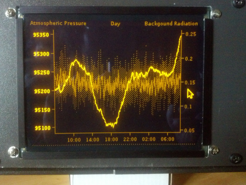
Raspberry Pi Java project to acquire, store, and display numerical data from different Channels over 5 different time scale. So far Atmospheric pressure and temperature with a BMP085 probe, Background Radiation with a serial Geiger counter, System load and memory usage of the operating system, temperature and brightness with an outside probe linked with nRF24L01+. Data are pushed online to be visualized with a google chart page :
http://muth.inc.free.fr/pilogger/index.php?scale=Day&grouped=0
Story of the project : http://pierremuth.wordpress.com/rpiadventure/
Linked with this hardware project : https://code.google.com/p/dvi-el-display/


| Qty | Value | Footprint | References |
|---|---|---|---|
| 10 | custom_footprints:BoardSolderSquare | , , , , , , , , , | |
| 4 | 10K | Resistors_SMD:R_0805_HandSoldering | R1, R2, R3, R4 |
| 3 | 2.2uF | Capacitors_SMD:C_0805_HandSoldering | C1, C2, C4 |
| 1 | + Batt | Socket_Strips:Socket_Strip_Straight_1x02 | + Batt |
| 1 | 0.22uF | Capacitors_SMD:C_0805_HandSoldering | C5 |
| 1 | 1K | Resistors_SMD:R_0805_HandSoldering | R5 |
| 1 | 1uF | Capacitors_SMD:C_0805_HandSoldering | C3 |
| 1 | ADC | Measurement_Points:Measurement_Point_Square-SMD-Pad_Small | adc |
| 1 | ESP-12E | custom_footprints:ESP-12E | U3 |
| 1 | G0 | Measurement_Points:Measurement_Point_Square-SMD-Pad_Small | 0 |
| 1 | G10 | Measurement_Points:Measurement_Point_Square-SMD-Pad_Small | 10 |
| 1 | G12 | Measurement_Points:Measurement_Point_Square-SMD-Pad_Small | 12 |
| 1 | G13 | Measurement_Points:Measurement_Point_Square-SMD-Pad_Small | 13 |
| 1 | G14 | Measurement_Points:Measurement_Point_Square-SMD-Pad_Small | 14 |
| 1 | G15 | Measurement_Points:Measurement_Point_Square-SMD-Pad_Small | 15 |
| 1 | G16 | Measurement_Points:Measurement_Point_Square-SMD-Pad_Small | 16 |
| 1 | G2 | Measurement_Points:Measurement_Point_Square-SMD-Pad_Small | 2 |
| 1 | G4 | Measurement_Points:Measurement_Point_Square-SMD-Pad_Small | 4 |
| 1 | G5 | Measurement_Points:Measurement_Point_Square-SMD-Pad_Small | 5 |
| 1 | G9 | Measurement_Points:Measurement_Point_Square-SMD-Pad_Small | 9 |
| 1 | LOGO | custom_footprints:LOGO | |
| 1 | LP38692 | custom_footprints:SOT-223-5 | U1 |
| 1 | Mode | GS3 | Mode |
| 1 | REG710 | TO_SOT_Packages_SMD:SOT-23-6 | U2 |
| 1 | RST | Measurement_Points:Measurement_Point_Square-SMD-Pad_Small | rst |
| 1 | Red | LEDs:LED_0805 | D1 |
| 1 | Reset | Buttons_Switches_SMD:SW_SPST_FSMSM | reset |
| 1 | Serial T R G | Socket_Strips:Socket_Strip_Straight_1x03 | Serial T R G |
| 1 | Sharp_Memory_LCD | custom_footprints:10pins_0.5mm_PITCH_connector_FPC | LCD |
| 1 | com | GS2 | com |
| 1 | prog run | Switch_SP3T | prog run |
| 1 | wake | GS2 | wake |


SonarSquad/OASIS
Code, schematics and readme file for the OASIS sonar bachelor thesis

UtilitechAS/amsreader-firmware
ESP8266 and ESP32 compatible firmware to read, interpret and publish data to MQTT from smart electrical meters, both DLMS and DSMR is supported


skorokithakis/tiny-ESP8266-breakout
A very small and basic ESP8266 breakout board

mcbittech/souliss-smart-thermostat-WiFi
ESP8266 WiFi Smart Thermostat based on Souliss IoT Framework

girst/hardpass-passwordmanager-mirror-of-git.gir.st
https://git.gir.st/hardpass.git - Seldomly Updated Mirror: Hardpass is a Raspberry Pi Zero based hardware password manager, using passwordstore.org.

MakerMeik/Window-Sensor
Here you will find all the files you need to build an ESP8266-based window sensor whose battery will last for several years. Have a look at my video on Youtube: https://youtu.be/vxbuO1zWo3w

It measures 60 × 20 mm and has 2 copper layers, 1.6 mm thick.
46 parts, built around the ESP-12E, LP38692NDC and G15. The full list of its parts is on this page, with links to each part's symbol and footprint where PCBKit's library has them.
From the pierre-muth/pilogger repository on GitHub, at the commit this page was made from: the board is WifiLCD/Kicad/wifiLCD.kicad_pcb. PCBKit opens the board in the browser, with nothing to install.
Its repository states no licence, so its author keeps all rights: ask pierre-muth before reusing the design.