
2 layers85 × 56 mm
Curiosity Nano Full bridge module rev1
SonarSquad/OASIS
Code, schematics and readme file for the OASIS sonar bachelor thesis
23 parts

 SonarSquad/OASIS
Code, schematics and readme file for the OASIS sonar bachelor thesis
Oasis ADC is an open-source printed circuit board by SonarSquad, from the SonarSquad/OASIS repository on GitHub. It is a 2-layer board of 65 × 56 mm with 50 parts on 63 nets, routed with 440 tracks and 225 vias.
It is built around the ADA4841-2YR and LP38692NDC. Its parts include 19 capacitors, 10 resistors, 5 ICs, 5 connectors and 2 diodes.
Contains the complete code, circuit schematics and designs for the OASIS prototype system. The full OASIS - A low-cost modular echosounder thesis report should also be red for a better understanding if further development of the system are to be investigated.
CONTENT: folder and content
HARDWARE modules:
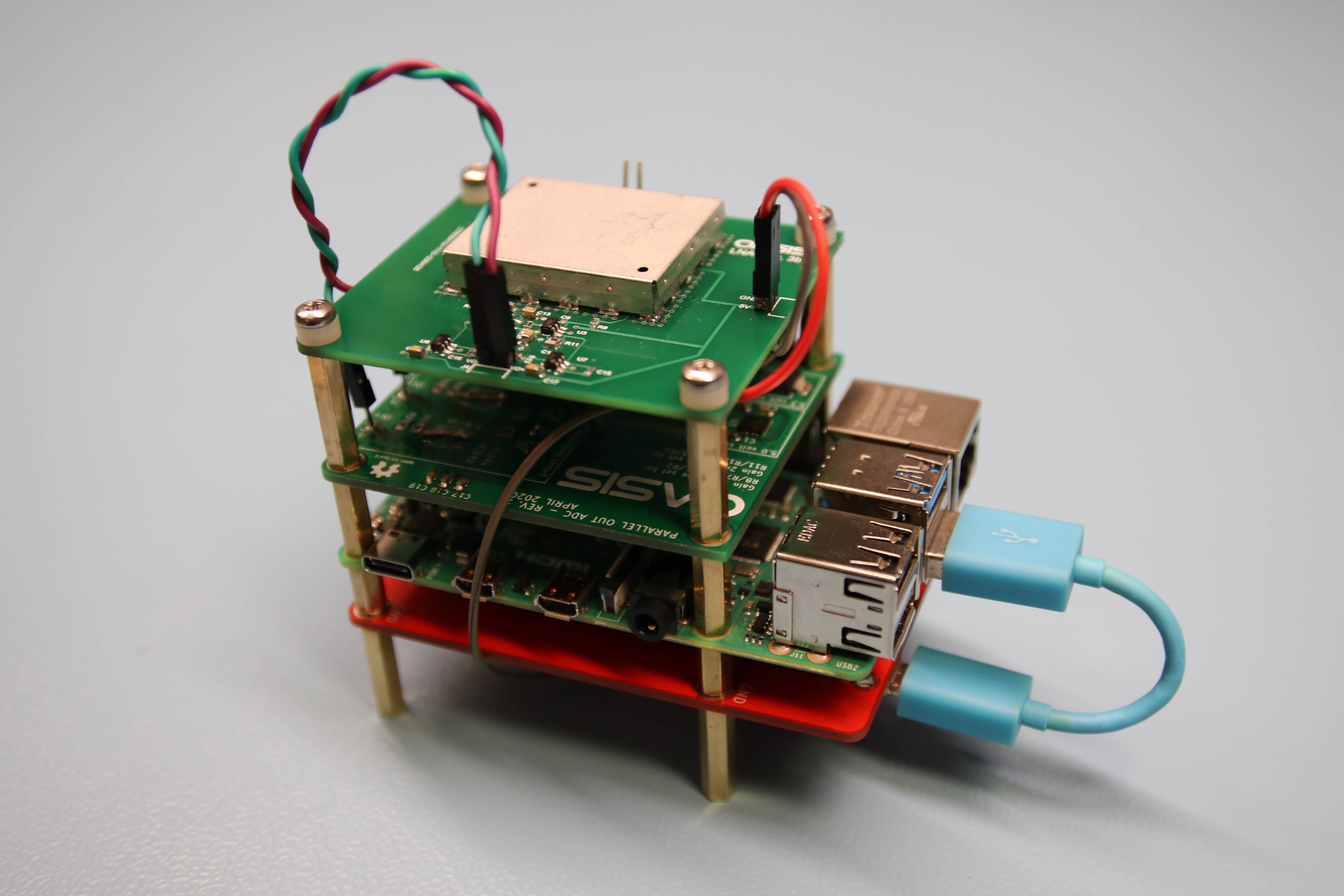
OASIS Prototype achievements:
System startup, Transmit a pulse at preset frequency (200kHz).
Amplify returning echo with LNA.
Sample returning echo, (switch not developed yet - two transducers used while testing, one for transmit and one for receive).
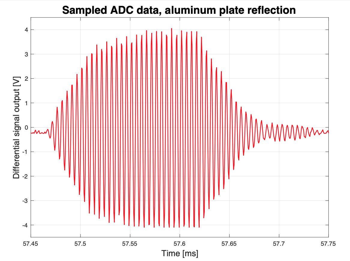
Plotting and light processing of received signal.
CONTACT:
| Qty | Value | Footprint | References |
|---|---|---|---|
| 9 | 1µF | Capacitor_SMD:C_0603_1608Metric_Pad1.05x0.95mm_HandSolder | C3, C4, C5, C7, C9, C10, C11, C15, C16 |
| 8 | R | Resistor_SMD:R_0805_2012Metric | R1, R2, R3, R4, R7, R8, R11, R12 |
| 3 | 0.1µF | Capacitor_SMD:C_0603_1608Metric_Pad1.05x0.95mm_HandSolder | C6, C8, C12 |
| 3 | 4.7µF | Capacitor_SMD:C_0603_1608Metric_Pad1.05x0.95mm_HandSolder | C1, C2, C19 |
| 2 | 12 ohm | Resistor_SMD:R_0805_2012Metric | R5, R6 |
| 2 | 4.7µF | Capacitor_SMD:C_0805_2012Metric | C17, C18 |
| 2 | ADA4841-2 | Package_SO:SOIC-8_3.9x4.9mm_P1.27mm | U4, U5 |
| 2 | Conn_01x01 | Connector_PinHeader_2.54mm:PinHeader_1x01_P2.54mm_Vertical | J4, J5 |
| 2 | D_Zener_ALT | Diode_SMD:D_SOD-323 | D1, D2 |
| 1 | 10nF | Capacitor_SMD:C_0603_1608Metric_Pad1.05x0.95mm_HandSolder | C13 |
| 1 | 220pF | Capacitor_SMD:C_0603_1608Metric_Pad1.05x0.95mm_HandSolder | C14 |
| 1 | ADS8422 | TorCustomFootprints:ADS8422 | U1 |
| 1 | Conn_01x02 | Connector_PinHeader_2.54mm:PinHeader_1x02_P2.54mm_Vertical | J6 |
| 1 | Conn_01x07 | Connector_PinHeader_2.54mm:PinHeader_1x07_P2.54mm_Vertical | J3 |
| 1 | Conn_02x20_Odd_Even | Connector_PinHeader_2.54mm:PinHeader_2x20_P2.54mm_Vertical | J1 |
| 1 | LOGO | TorCustomFootprints:Oasis_logo_30mm | G*** |
| 1 | LP2988-5.0_WSON8 | Package_SON:WSON-8_4x4mm_P0.8mm | U3 |
| 1 | LP38692 | Package_TO_SOT_SMD:SOT-223-5 | U2 |
The 42 most common of 50 parts.
SonarSquad/OASIS
Code, schematics and readme file for the OASIS sonar bachelor thesis


hackclub/OnBoard
💡 Join 1,000 teenagers and make your first PCB with a $100 grant!

dmcke5/NucDeck
The Open Source DIY Handheld Gaming PC!

It measures 65 × 56 mm and has 2 copper layers, 1.6 mm thick.
50 parts, built around the ADA4841-2YR and LP38692NDC. The full list of its parts is on this page, with links to each part's symbol and footprint where PCBKit's library has them.
From the SonarSquad/OASIS repository on GitHub, at the commit this page was made from: the board is Oasis_ADC_PCB/Oasis_ADC.kicad_pcb. PCBKit opens the board in the browser, with nothing to install.
Its repository states no licence, so its author keeps all rights: ask SonarSquad before reusing the design.