2 layers127 × 114.3 mm

 pierre-bouckson/peter_pan
ESP32 quadcopter flight controller (X frame), flown over WiFi from a PC with a PS4 gamepad. The repository holds two parts:
Peter pan is an open-source printed circuit board by pierre-bouckson, from the pierre-bouckson/peter_pan repository on GitHub. It is a 2-layer board of 81.8 × 81.8 mm with 24 parts on 34 nets, routed with 77 tracks and 16 vias.
It is built around the R-78E3.3-0.5, ERJ3GEYJ103V and VJ0603V104ZXAPW1BC, with the M20-7821546 among its other parts. Its parts include 7 connectors, 4 capacitors, 3 resistors and 1 IC.


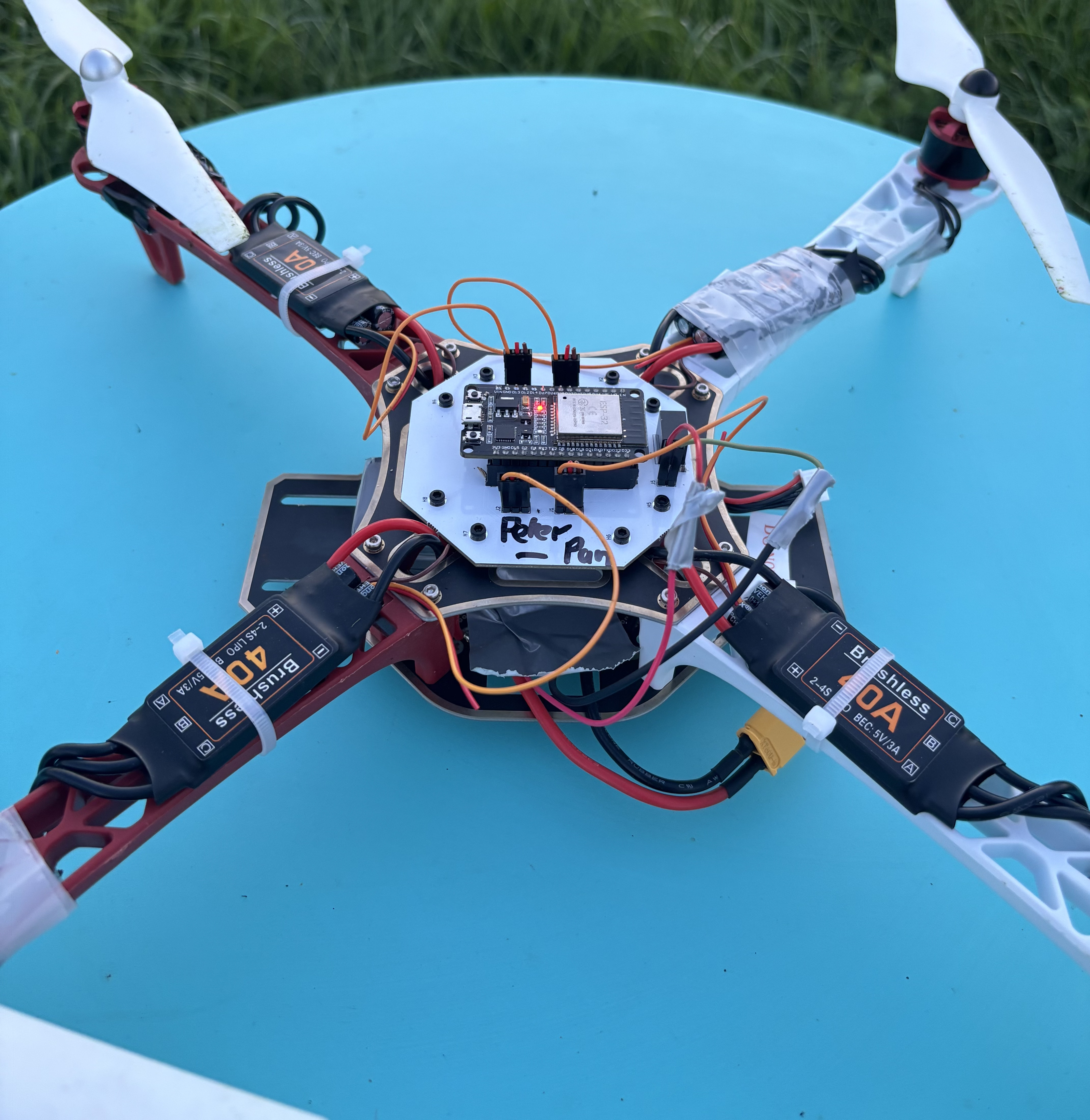
ESP32 quadcopter flight controller (X frame), flown over WiFi from a PC with a PS4 gamepad. The repository holds two parts:
| Folder | Content |
|---|---|
firmware/ | PlatformIO / Arduino-ESP32 firmware running on FreeRTOS |
python_tool/ | PC-side tools: gamepad pilot with live PID tuning, ESC calibration |
PCB/ | KiCad 9 carrier board (schematic, layout, libraries, JLCPCB files) |
 PS4 gamepad ──USB──► PC (gamepad_pilot.py) ──UDP 8889──► ESP32 (WiFi AP "peter_pan")
                            ▲                                  │
                            └──── UDP 8894 telemetry ◄─────────┤
└──── UDP 8895 debug ◄─────────┘| Qty | Part | Reference |
|---|---|---|
| 1 | Frame | HAWK'S WORK F450, 450 mm, with standard landing gear |
| 4 | Motors | HAWK'S WORK 2212 920KV brushless, 2–4S (2 × CW + 2 × CCW) |
| 4 | ESCs | RUIZHI 40A brushless ESC, 2–4S, BEC 5V/3A |
| 1 set | Propellers | Tbest self-locking propellers, CW/CCW, 8-piece set |
| 1 | Battery | Tattu LiPo 3S 11.1 V 2300 mAh 45C |
| 1 | Charger | Haisito B3 LiPo charger, 2S/3S |
| 1 | Flight controller | ESP32 DevKit V1 (30 pins) on the custom carrier board (see PCB) |
| 1 | IMU | ST LSM6DSOX (LSM6DSOTR), soldered on the PCB |
| 1 | Regulator | RECOM R-78E3.3-0.5, soldered on the PCB |
| 8 | Screws | M2.5, to mount the PCB on the frame |
| 1 | Gamepad | Sony PS4 DualShock 4, USB |
| Part | Detail |
|---|---|
| MCU | ESP32 DevKit (esp32dev) |
| IMU | LSM6DSOX (accelerometer + gyroscope) on I2C, SDA = 21, SCL = 22 |
| Motors | 4 ESCs, servo-style signal 1000–2000 µs at 400 Hz |
| Motor pins | M1 = GPIO 13, M2 = GPIO 33, M3 = GPIO 23, M4 = GPIO 15 |
| Status LED | GPIO 2 (off = motors cut by stop / emergency) |
M1/M2 are on the right side, M3/M4 on the left. M1 and M3 spin
counter-clockwise (see YAW_DIR in firmware/lib/control/flight_controller.h).
Custom 2-layer carrier board (KiCad project in PCB/, fabrication files for
JLCPCB included). On board:
⚠️ The middle pin of the ESC headers is the 3.3 V rail: leave the red (BEC 5 V) wire of the ESC cables disconnected. The PCB header numbers do not match the firmware motor numbers — J1 → M3, J2 → M4, J3 → M1, J4 → M2.
| Module | Role |
|---|---|
src/main.cpp | Entry point, FreeRTOS tasks, safety, telemetry |
include/AppConfig.h | WiFi SSID / password and UDP ports |
lib/IMU | LSM6DSOX driver, calibration, Kalman filter, tilt emergency |
lib/PID | Generic PID |
lib/control | Cascaded angle → rate loop, X-frame motor mixing, yaw |
lib/motor | LEDC PWM outputs for the ESCs |
lib/wifi | WiFi access point + UDP transport |
lib/comm | Text command parser |
Roll and pitch use a cascaded controller: an outer attitude loop (angle) feeds a setpoint to an inner rate loop (angular velocity).
 ATTITUDE LOOP (outer, 200 Hz)        RATE LOOP (inner, 1 kHz)
 <--------------------------------> <------------------------------------------------------------------>

 stick setpoint (deg)          rate setpoint (deg/s)                         throttle x 2.5
                                                                                   |
        +             +-----+            +           +-----+        +-----+     +  v          +--------+
 ------->( X )------->|  K  |------------>( X )----->| PID |------->| MIX |----->( + )------->| Motors |
                      +-----+                        +-----+        +-----+                   +--------+
           ^ -                              ^ -
           |                                |
           | angle (deg)                    | rate (deg/s)
      +----------+                     +----------+
      |  Kalman  |                     |   Gyro   |
      +----------+                     +----------+
(accel + gyro)| Signal | Code |
|---|---|
| Angle error (°) = stick / 20 − Kalman angle | FlightController::error_angle() |
Rate setpoint (°/s) = K × angle error, K = ANGLE_TO_VELOCITY = 5 (P only) | angle_to_velocity() |
PID output per axis (telemetry CR, CP, CY) | correction_vel() → pid_rate_roll/pitch/yaw() |
| Per-motor duty (0–255) = mix of PID outputs + throttle × 2.5 | mix(), then vTaskRateLoop in main.cpp |
vTaskAttitudeLoop, 200 Hz, priority 1): reads the
Kalman-fused angles, compares them to the stick setpoint and turns the angle
error into a rotation-rate setpoint. It is a pure proportional gain: it only
decides how fast the drone should rotate to reach the desired angle.vTaskRateLoop, 1 kHz, priority 2): reads the gyro, compares
the measured rate to the setpoint and runs the PID whose gains are tuned
live from the gamepad tool (pid kp ki kd). The D term is computed on the
gyro measurement (not on the error), low-pass filtered, so a stick move does
not kick the output. The correction is mixed onto the four motors (X frame),
then the throttle is added.pidyaw kp ki) against the Z gyro. Centred stick = hold 0 °/s.loop(): receives commands, handles the stop/resume latch, sends telemetry at 20 Hz.Throttle at 0 cuts the motors and resets the PIDs; tilt beyond 60° cuts
the motors until the drone is back under 30°; a stop command latches the
motors off until resume; a 30 s watchdog reboots the board if loop() hangs.
Edit firmware/include/AppConfig.h before building:
const char* ssid = "peter_pan";          // access point created by the ESP32
const char* password = "pierre qui vole";
uint16_t localPort = 8889;               // commands  (PC -> drone)
uint16_t hostPort  = 8894;               // telemetry (drone -> PC)
If you change the ports, update CMD_PORT / TELEMETRY_PORT in the Python tools as well.
Requirements: PlatformIO — either the VS Code
extension or the CLI (pip install platformio). Dependencies (Arduino-ESP32,
Adafruit LSM6DS, …) are downloaded automatically on the first build.
cd firmware

# Build
pio run

# Flash (plug the ESP32 over USB)
pio run -t upload

# Serial monitor, 115200 baud
pio device monitor
If several serial ports are present, pick one explicitly:
pio device list
pio run -t upload --upload-port /dev/cu.usbserial-XXXX
If the upload does not start ("Connecting....."), hold the BOOT button on
the ESP32 until writing begins. Upload speed is set to 921600 baud in
platformio.ini; lower upload_speed if the transfer is unreliable.
In VS Code, the same actions are available from the PlatformIO toolbar (✓ Build, → Upload, 🔌 Monitor).
At boot the drone must lie flat and still: the IMU is calibrated in
setup()and the ESCs are held at idle for 3 s so they can arm.
Commands are plain text, sent to 192.168.4.1:8889:
| Command | Effect |
|---|---|
command | Ping, the drone answers ok on port 8894 |
rc <left> <forward> <up> <yaw> | Pilot command. left/forward: ±400 (÷20 → ±20° setpoint); up: throttle 0–100 (× 2.5 → duty); yaw: ±400 (→ ±180 °/s) |
pid <kp> <ki> <kd> | Roll / pitch rate PID gains |
pidyaw <kp> <ki> | Yaw PI gains |
stop | Emergency stop, latched |
resume | Clears the emergency stop |
Telemetry is broadcast at 20 Hz on 192.168.4.255:8894:
ROLL: 1.23 deg, PITCH: -4.56 deg | RA:1.10 PA:-4.30 | CR:2.10 CP:-3.40 | M1:5 M2:-1 M3:-5 M4:1 | GZ:-8.20 CY:3.10 | HZ:1000| Field | Meaning |
|---|---|
ROLL/PITCH | Kalman-fused angles (°) |
RA/PA | Raw accelerometer angles, before filtering (°) |
CR/CP | Roll / pitch PID outputs |
M1..M4 | PID contribution per motor, throttle excluded |
GZ | Measured yaw rate (°/s) |
CY | Yaw PI output |
HZ | Actual rate loop frequency |
Debug messages (radio.my_printf(...)) are broadcast separately on port 8895.
Python 3.10+ is required.
cd python_tool
python3 -m venv venv
./venv/bin/pip install -r requirements.txt
Dependencies: pygame-ce (gamepad), PyQt5 + pyqtgraph (GUI and plots),
numpy, colorama.
Before running any tool, connect the PC to the peter_pan WiFi network
created by the ESP32. The drone is always at 192.168.4.1.
| File | Role |
|---|---|
gamepad_pilot.py | Flight GUI: gamepad control, live PID tuning, plots, CSV logs |
udp_link.py | Telemetry / debug UDP receivers and telemetry line parser |
esc_calibration.py | Guided ESC throttle-range calibration |
cd python_tool
./venv/bin/python gamepad_pilot.py
Plug a PS4 DualShock 4 controller over USB (before or after launch — use
"Rechercher la manette" to rescan). The tool sends rc commands at 50 Hz
and refreshes the GUI at ~30 Hz.
| Input | Action |
|---|---|
| Left stick, vertical | Throttle |
| Left stick, horizontal | Yaw |
| Right stick | Roll / pitch (push forward = nose down, fly forward) |
| △ Triangle | Arm — throttle stays at 0 until armed |
| ○ Circle | Disarm (tool side), immediately sends rc 0 0 0 0 |
| ✕ Cross | Emergency stop: sends stop, firmware cuts the motors and latches |
| □ Square | Resume: sends resume, then re-arm with △ to get throttle back |
| L1 (held) | Fine throttle mode: throttle change rate divided by 5 |
| D-pad ← / → | Yaw Kp − / + (step 0.02) |
| D-pad ↓ / ↑ | Yaw Ki − / + (step 0.01) |
Unplugging the gamepad while armed disarms automatically and keeps sending
zero throttle. stop / resume are repeated 5 times since UDP is unreliable.
The throttle curve exponent (1.0 = linear, 2.5 default, up to 4.0) and the incremental rate can be adjusted in the GUI to get finer control around hover.
pid), no reflash needed.pidyaw).Logs are written to python_tool/logs/vol-<timestamp>.csv, one row per
telemetry frame (~20 Hz): IMU angles, setpoints and errors, PID gains in use,
corrections and arming state. Header lines start with #:
import pandas as pd
df = pd.read_csv("logs/vol-....csv", comment="#")Axis and button indices depend on the OS / driver. If an axis is swapped or
inverted, check the raw values in the Manette panel and edit the constants
at the top of gamepad_pilot.py:
AX_YAW, AX_THROTTLE, AX_ROLL, AX_PITCH = 0, 1, 2, 3
BTN_STOP, BTN_ARM, BTN_DISARM, BTN_RESUME = 0, 3, 1, 2   # Cross / Triangle / Circle / Square
BTN_FINE = 4                                             # L1
STICK_TO_ANGLE and THROTTLE_GAIN are copied from the firmware for logging;
keep them in sync if you change flight_controller.h.
Teaches the four ESCs the 1000–2000 µs throttle range so the motors start together.
cd python_tool
./venv/bin/python esc_calibration.py            # guided procedure
./venv/bin/python esc_calibration.py --dry-run  # rehearsal, sends nothing
Options: --ip (default 192.168.4.1), --max / --min (percent, default 100 / 0).
The script walks you through each step and waits for confirmation:
Ctrl-C at any time brings the motors back to 0 % before exiting.
⚠️ This tool relies on an
esc <percent>command that is not yet implemented infirmware/lib/comm/command_parser.cpp. It must be added to the firmware before the calibration can work.
YAW_DIR) at yaw Kp = 0.05.| Qty | Value | Footprint | References |
|---|---|---|---|
| 8 | MountingHole_Pad | MountingHole:MountingHole_2.5mm_Pad | H1, H2, H3, H4, H5, H6, H7, H8 |
| 3 | 10k | Resistor_SMD:R_0603_1608Metric | R1, R2, R3 |
| 2 | 100n | Capacitor_SMD:C_0603_1608Metric | C2, C3 |
| 2 | Conn_01x15_Pin | Connector_PinHeader_2.54mm:PinHeader_1x15_P2.54mm_Vertical | J6, J7 |
| 1 | 10u | Capacitor_SMD:C_0603_1608Metric | C4 |
| 1 | 10u | Capacitor_SMD:C_0805_2012Metric | C1 |
| 1 | Alim | Connector_PinHeader_2.54mm:PinHeader_1x02_P2.54mm_Vertical | J5 |
| 1 | LSM6DSOTR | imu:LSM6DSOTR | U2 |
| 1 | Motor1 | Connector_PinHeader_2.54mm:PinHeader_1x03_P2.54mm_Vertical | J1 |
| 1 | Motor2 | Connector_PinHeader_2.54mm:PinHeader_1x03_P2.54mm_Vertical | J2 |
| 1 | Motor3 | Connector_PinHeader_2.54mm:PinHeader_1x03_P2.54mm_Vertical | J3 |
| 1 | Motor4 | Connector_PinHeader_2.54mm:PinHeader_1x03_P2.54mm_Vertical | J4 |
| 1 | R-78E3.3-0.5 | reg:CONV_R-78E3.3-0.5 | PS1 |

OpenModbus/OM-64DO
A compact industrial-grade 64-channel Modbus RTU output module.


rafkhan/lowstepper
Dual phase manipulation low frequency oscillator by Okay Synthesizer.


Th3Link/tanklevel
This project provides a solution for measuring the liquid level in tanks, such as rainwater tanks, using the TL-136 pressure sensor.

OpenModbus/OM-16LED
A compact industrial-grade 16-channel Modbus RTU LED driver.
It measures 81.8 × 81.8 mm and has 2 copper layers, 1.6 mm thick.
24 parts, built around the R-78E3.3-0.5, ERJ3GEYJ103V, VJ0603V104ZXAPW1BC and M20-7821546. The full list of its parts is on this page, with links to each part's symbol and footprint where PCBKit's library has them.
From the pierre-bouckson/peter_pan repository on GitHub, at the commit this page was made from: the board is PCB/PCB.kicad_pcb and its schematic PCB/PCB.kicad_sch. PCBKit opens the board in the browser, with nothing to install.
Its repository states no licence, so its author keeps all rights: ask pierre-bouckson before reusing the design.