Skip to the content
PCBKitNew board
2 layers49 × 90.1 mmVers2 cheaper, the printed circuit board in 3D

DEFCON 25 Badge 2017

Size
49 × 90.1 mm
Copper layers
2
Thickness
1.6 mm
Parts
19
Nets
40
Pads
72
Tracks, vias
194, 0
Routed
Yes
KiCad
KiCad 4
Created
4 Jul 2017
Updated
15 Oct 2019

Overview

Vers2 cheaper is an open-source printed circuit board by pidren, from the pidren/defconbadge2017 repository on GitHub, published under the MIT licence. It is a 2-layer board of 49 × 90.1 mm with 19 parts on 40 nets, routed with 194 tracks and 0 vias.

Its parts include 11 resistors, 5 diodes and 3 connectors.

README

README.md

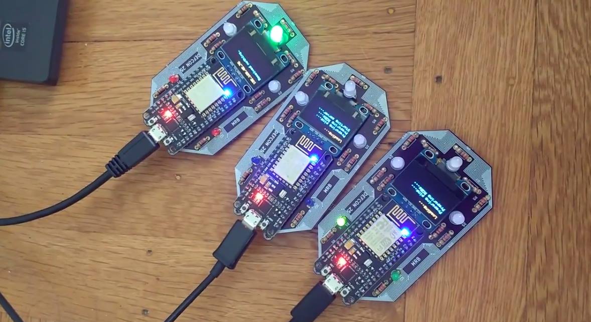
DEFCON 25 Custom Badge

Custom PCB design and code for DefCon 25 badge. Credits to @mschuldt for help with the PCB design.

Demo Video

Link to Demo Video

Why was this built?

For fun. Also I just wanted to learn how to do something I don't know how to do. At all.

Designing the Custom PCB

Coming up with the final design took about 5 months of continuous redesigning and prototyping. It also took a long time mostly because I didn't know anything about EE before this project. :) The main goals of the PCB was that we would be able to fit all the components desired within the smallest surface area possible, while also looking pleasant and something you'd want to wear around your neck.

What does it do?

  • Each individual badge will connect to (unfortunately) hardcoded WiFi network.
  • Once connected to a WiFi network, the badges will try to find their "sibling" badges by broadcasting itself on the network.
  • A badge will never learn a sibling badge twice, but will try to find as many nearby siblings as possible.
  • When a badge knows of at least one sibling in nearby viscinity it will start communicating.
  • All badges will communicate to each other independently, and all badges will communicate to all other badges that is learned.

Required Components for Assembly (per badge)

How to Assemble

  • Basically solder on all the parts.
  • Flash ESP with the arduino code using Arduino IDE version 1.6.4 and above
    • To compile correctly, you must have these libraries installed:
      • Adafruit_GFX_Library
      • Adafruit_SSD1306 Library
      • Use board manager to install ESP modules. You'll be using the NodeMCU 1.0 ESP 12E board module.
    • You must flash in NodeMCU 1.0 ESP 12E mode. This mode has all the settings you need for the board so you should not have to touch anything.
  • The battery does need manual assembly:
    • Clip off the JST end off of the LiPoly battery and solder onto the male microUSB part.

Useful Links

Parts

19
QtyValueFootprintReferences
1110kResistors_ThroughHole:Resistor_Horizontal_RM7mmR1, R2, R3, R4, R5, R6, R7, R8, R9, R10, R11
3LED_RCBGLEDs:LED-RGB-5MM_Common_CathodeD3, D4, D5
2CONN_01X15Pin_Headers:Pin_Header_Straight_1x15P2, P3
2LEDLEDs:LED-3MMD1, D2
1CONN_01X4Pin_Headers:Pin_Header_Straight_1x04P1

Questions

How big is the Vers2 cheaper PCB?

It measures 49 × 90.1 mm and has 2 copper layers, 1.6 mm thick.

What parts does the Vers2 cheaper use?

19 parts. The full list of its parts is on this page, with links to each part's symbol and footprint where PCBKit's library has them.

Where can I download the Vers2 cheaper KiCad files?

From the pidren/defconbadge2017 repository on GitHub, at the commit this page was made from: the board is vers2_cheaper.kicad_pcb. PCBKit opens the board in the browser, with nothing to install.

Can I use the Vers2 cheaper design in my own project?

Its repository publishes it under the MIT licence: you may reuse it on that licence's terms (keep the author's notice, and for a copyleft licence share your changes alike).

Similar boards

  • 2 layers43.9 × 27.7 mmTcd1304-4v, the printed circuit board in 3D

    Tcd1304-4v

    OpnTec/open-spectrometer-hardware

    Open source VIS spectrometer

    19 parts1.5k
  • 2 layers50 × 60 mmDebate Device, the printed circuit board in 3D

    Debate Device

    hackclub/OnBoard

    💡 Join 1,000 teenagers and make your first PCB with a $100 grant!

    19 parts915
  • 2 layers102.9 × 96.7 mmISA adapter, the printed circuit board in 3D

    ISA adapter

    polpo/picogus

    Emulation of ISA sound cards and CD-ROM on Raspberry Pi Pico (GUS, SB/Adlib, MPU-401, Tandy, CMS, Panasonic CD-ROM) with USB mouse/joystick support

    19 parts805
  • 2 layers60 × 39 mmPs2usb, the printed circuit board in 3D

    Ps2usb

    rasteri/HIDman

    Adapting USB devices to work on old computers

    19 parts432
  • 2 layers70.1 × 43.2 mmIaq device, the printed circuit board in 3D

    Iaq device

    nkitanov/iaq_board

    IAQ Board is a DIY (Do-It-Yourself) device for measuring internal air quality

    19 parts396
  • 2 layers80 × 80 mmGB BRK CPU G1, the printed circuit board in 3D

    GB BRK CPU G1

    Gekkio/gb-hardware

    Game Boy -related custom hardware by gekkio

    19 parts379CC-BY-4.0
  • 2 layers25.4 × 25.4 mmIna169, the printed circuit board in 3D

    Ina169

    Ardumower/ardumower

    Develop an open source robotic lawn mower (HW+SW reference platform)

    19 parts282
  • 2 layers58.4 × 28.6 mmNew rele, the printed circuit board in 3D

    New rele

    zmaker/arduino_cookbook

    gli sketch del nuovo progetto Arduino Cookbook e dei video di YouTube

    19 parts269