
4 layers28 × 80 mm
ESP32-PoE Rev M
OLIMEX/ESP32-POE
ESP32 IoT development board with 100Mb Ethernet and 802.3 Power Over Ethernet (POE)
142 parts415Apache-2.0

 PickledDog/rc-fabgl17
FabGL terminal board for RC2014
Rc fabgl is an open-source printed circuit board by PickledDog, from the PickledDog/rc-fabgl repository on GitHub, published under the Apache-2.0 licence. It is a 2-layer board of 99.1 × 49.9 mm with 47 parts on 113 nets, routed with 319 tracks and 41 vias.
It is built around the ESP32-WROVER-E(4MB). Its parts include 20 resistors, 7 capacitors, 5 connectors, 3 ICs and 2 transistors. It belongs with the radio and wireless boards and the ESP32 boards of this library.
FabGL terminal board for RC2014
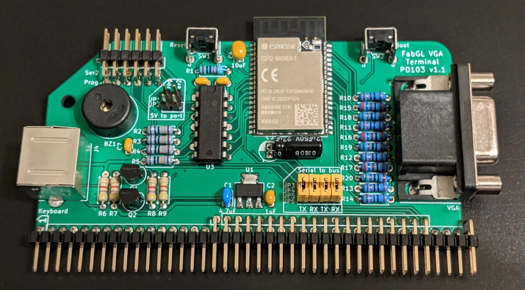
This is my take on the FabGL dev kit, designed into the form factor of a RC2014 card with the intention of implementing a serial terminal.
FabGL is an excellent graphics/UI/Human Interface library for the Espressif ESP32. It provides VGA display generation, PS2 keyboard/mouse support, audio, and terminal emulation abilities. This gives us everything we need to build a serial terminal (and even provides examples to do just this). In addition, the ESP32 is first and foremost a WiFi module, opening up the possibility of "dial" in/out cabibilities.
The common ESP32-WROOM module starts to run a bit short on memory when implementing a terminal, so the ESP32-WROVER is used instead - this adds an extra 8MB of RAM for us to use. The module is hooked up as described in Espressif's datasheet, with RC reset circuit and appropriate bypass caps.
The standard dev kit schematic provides VGA, PS/2 keyboard, PS/2 mouse and line-level audio. The mouse port is removed, audio is sent directly into a piezo buzzer, and level-shifted serial ports are added to connect to the 5V serial ports of RC2014 systems. In addition, improvements have been made to the other peripheral connections.
120Ω resistors are added to terminate the VGA connection (and limit the HSync and VSync pins). The design is similar to the Parallax Propeller VGA breakout. The resistor values were picked to stay within the drive capabilities of the ESP32 (which is why the correct 75Ω resistors weren't an option).
The resistor PS/2 level-shifters are replaced with MOSFET shifters.
Audio won't be used for much more than a terminal bell - as such, it's just connected to a buzzer. Make sure a piezo buzzer is used - the ESP32 can't drive a dynamic one without help.
Serial ports are connected to the remaining pins on the ESP32. There are enough pins to implement two serial ports, with RTS/CTS flow control on the second port. Incoming 5V signals are shifted down to 3.3V with a 74LV125.
The standard RX/TX pins of the ESP32 are broken out to a standard "FTDI-style" header for programming. RESET and BOOT are connected to buttons on the top of the card.
The terminal board uses the RC2014 bus for little more than power and to connect to the bus serial ports. Jumpers are provided to disconnect the ports from the bus as needed. The Ser1 interface is provided to the bus only, while Ser2 is available on both the (Enhanced) bus and an FTDI-style header. Only the header provides the RTS & CTS pins. Since Ser2 is the only thing on the Enhanced bus, consider the wider connector optional - a cheaper 1x40 header can be used in place of the 2x40 one (you'll need a 6-pin Dupont cable to hook up Ser2).
The ESP32 module will need to be programmed before use - this is done using an FTDI adapter on the assembled board, via the Prog port. If you don't have an FTDI adapter, they can be found on eBay. I don't have a firmware bundle made up for this yet, so for now consider this a dev kit for hacking (as opposed to a plug-and-play terminal board). To get started with FabGL, check out Fabrizio Di Vittorio's YouTube channel and the FabGL reference. Compiling FabGL and its examples requires the Arduino IDE. Once Arduino is up and running, follow the instructions in Fabrizio's video to add the ESP32 board package and FabGL library. Be sure to select ESP32 Wrover Module from Tools → Board → ESP32 Arduino. Examples are found in File → Examples → FabGL → VGA.
Bill Of Materials and part references are below. If you want the 60-pin RC2014 Enhanced bus connector, you'll need to make it from a 2x40-pin right-angle header and pull out half of the pins from the top row (needle-nose pliers work well). I recommend using gold-plated header for this - I use these ones from Pololu or Sparkfun. The jumper headers can be snapped from regular (or double-row) breakaway header, for which eBay is substantially cheaper; the Mouser listings are provided for convenience.
The specified parts are just the ones I used, and can be substituted as needed - Mouser links provided for convenience and reference.
| Reference | Value | Qty | Mouser link |
|---|---|---|---|
| BZ1 | Piezo buzzer | 1 | TDK PS1240P02BT |
| C1 | 4.7μF ceramic | 1 | TDK FG18X5R1E475KRT06 |
| C2 | 1μF ceramic | 1 | TDK FG18X5R1H105KRT06 |
| C3 | 22μF electrolytic | 1 | KEMET ESS226M016AC2AA |
| C4 | 10μF ceramic | 1 | TDK FG18X5R1E106MRT06 |
| C5-C7 | 100nF ceramic | 3 | KEMET C315C104M5U5TA |
| J1/2 | 2x40 right-angle header | 1 | 3M 2380-5121TG |
| J3 | 2x6 right-angle header | 1 | Amphenol 10129382-912002BLF |
| J4 | 6-pin Mini-DIN socket | 1 | Kycon KMDGX-6S-BS |
| J5 | D-Sub HD-15 Female | 1 | TE 2311763-1 |
| JP1/2 | 2x2 header | 1 | Amphenol 10129381-904002BLF |
| JP3/4/5/6 | 2x4 header | 1 | Amphenol 10129381-908002BLF |
| Q1, Q2 | 2N7000 enh N-MOSFET | 2 | ON Semi 2N7000 |
| R1 | 10kΩ resistor | 1 | Yageo CFR-25JT-52-10K |
| R2-R5 | 100kΩ resistor | 4 | Yageo CFR-25JT-52-100K |
| R6-R9 | 4k7Ω resistor | 4 | Yageo CFR-25JT-52-4K7 |
| R10-R14 | 120Ω resistor | 5 | Yageo MFR-25FTF52-120R |
| R15-R17 | 261Ω resistor | 3 | Yageo MFR-25FRF52-261R |
| R18-R20 | 510Ω resistor | 3 | Yageo MFR-25FTE52-510R |
| SW1, SW2 | Right-angle tact sw 3.9mm | 2 | C&K PTS645VL392LFS |
| U1 | MCP1825S-330 | 1 | Microchip MCP1825ST-3302E/DB |
| U2 | ESP32-WROVER-E | 1 | Espressif ESP32-WROVER-E(M213EH3264PH3Q0) |
| U3 | 74LV125 | 1 | TI SN74LV125AN |
| Qty | Value | Footprint | References |
|---|---|---|---|
| 5 | 120R | Resistor_THT:R_Axial_DIN0207_L6.3mm_D2.5mm_P7.62mm_Horizontal | R10, R11, R12, R13, R14 |
| 4 | 100k | Resistor_THT:R_Axial_DIN0207_L6.3mm_D2.5mm_P7.62mm_Horizontal | R2, R3, R4, R5 |
| 4 | 4k7 | Resistor_THT:R_Axial_DIN0207_L6.3mm_D2.5mm_P7.62mm_Horizontal | R6, R7, R8, R9 |
| 3 | 0.1uF | Capacitor_THT:C_Disc_D3.0mm_W1.6mm_P2.50mm | C5, C6, C7 |
| 3 | 261R | Resistor_THT:R_Axial_DIN0207_L6.3mm_D2.5mm_P7.62mm_Horizontal | R15, R16, R17 |
| 3 | 510R | Resistor_THT:R_Axial_DIN0207_L6.3mm_D2.5mm_P7.62mm_Horizontal | R18, R19, R20 |
| 2 | 2N7000 | Package_TO_SOT_THT:TO-92 | Q1, Q2 |
| 1 | Mounting_Holes:MountingHole_3.2mm_M3 | ||
| 1 | 10k | Resistor_THT:R_Axial_DIN0207_L6.3mm_D2.5mm_P7.62mm_Horizontal | R1 |
| 1 | 10uF | Capacitor_THT:C_Disc_D3.4mm_W2.1mm_P2.50mm | C4 |
| 1 | 1uF | Capacitor_THT:C_Disc_D3.0mm_W1.6mm_P2.50mm | C2 |
| 1 | 22uF | Capacitor_THT:CP_Radial_D5.0mm_P2.00mm | C3 |
| 1 | 4.7uF | Capacitor_THT:C_Disc_D3.4mm_W2.1mm_P2.50mm | C1 |
| 1 | 74LV125 | Package_DIP:DIP-14_W7.62mm_LongPads | U3 |
| 1 | Boot | Button_Switch_THT:SW_Tactile_SPST_Angled_PTS645Vx39-2LFS | SW2 |
| 1 | Bus RX | Connector_PinHeader_2.54mm:PinHeader_1x02_P2.54mm_Vertical | JP4 |
| 1 | Bus RX2 | Connector_PinHeader_2.54mm:PinHeader_1x02_P2.54mm_Vertical | JP6 |
| 1 | Bus TX | Connector_PinHeader_2.54mm:PinHeader_1x02_P2.54mm_Vertical | JP3 |
| 1 | Bus TX2 | Connector_PinHeader_2.54mm:PinHeader_1x02_P2.54mm_Vertical | JP5 |
| 1 | Buzzer | Buzzer_Beeper:Buzzer_TDK_PS1240P02BT_D12.2mm_H6.5mm | BZ1 |
| 1 | ESP32-WROVER-E | rc-fabgl:ESP32WROVERE | U2 |
| 1 | Keyboard | rc-fabgl:Mini-DIN-6-Socket | J4 |
| 1 | MCP1825S | Package_TO_SOT_SMD:SOT-223-3_TabPin2 | U1 |
| 1 | Prog | Connector_PinHeader_2.54mm:PinHeader_1x02_P2.54mm_Vertical | JP1 |
| 1 | RC2014 | Connector_PinHeader_2.54mm:PinHeader_1x39_P2.54mm_Vertical | J1 |
| 1 | RC2014_Enh | Connector_PinHeader_2.54mm:PinHeader_1x20_P2.54mm_Vertical | J2 |
| 1 | Reset | Button_Switch_THT:SW_Tactile_SPST_Angled_PTS645Vx39-2LFS | SW1 |
| 1 | Ser2 | Connector_PinHeader_2.54mm:PinHeader_1x02_P2.54mm_Vertical | JP2 |
| 1 | Serial | Connector_PinHeader_2.54mm:PinHeader_2x06_P2.54mm_Horizontal | J3 |
| 1 | VGA | rc-fabgl:DSUB-15-HD_Female_Horizontal_P2.29x2.54mm_Housed | J5 |
It measures 99.1 × 49.9 mm and has 2 copper layers, 1.6 mm thick.
47 parts, built around the ESP32-WROVER-E(4MB). The full list of its parts is on this page, with links to each part's symbol and footprint where PCBKit's library has them.
From the PickledDog/rc-fabgl repository on GitHub, at the commit this page was made from: the board is rc-fabgl.kicad_pcb. PCBKit opens the board in the browser, with nothing to install.
Its repository publishes it under the Apache-2.0 licence: you may reuse it on that licence's terms (keep the author's notice, and for a copyleft licence share your changes alike).
OLIMEX/ESP32-POE
ESP32 IoT development board with 100Mb Ethernet and 802.3 Power Over Ethernet (POE)


Circuit-Digest/MLX90640-Thermal-Camera
An Open Source Thermal Imaging IR camera that you can build yourserlf

espena/broadcast-clock
Digital precision studio/broadcast masterclock with WiFi configuration, acts as local NTP server with accurate GPS time sync.

martinroger/ipodesp32
An iPod emulator for 2006-2013 BMW Mini Coopers that need Bluetooth

