8 layers120 × 100 mm
 Phylex/MotorControl
MotorControl ============ This Repository has the Kicad source files for an H-Bridge that I want to use in my model RC Boats. It is based around the DRV8701P H-Bridge driver Chip.
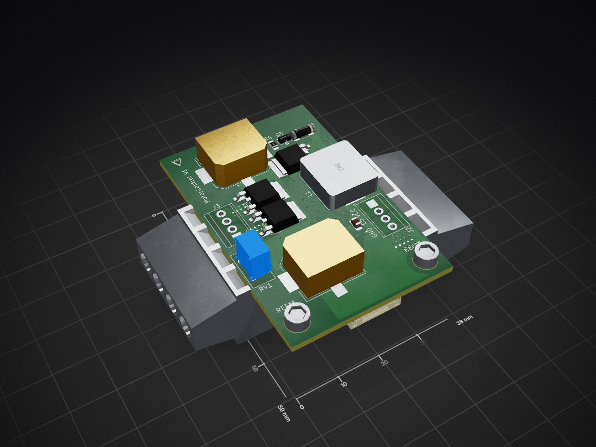
MotorControl is an open-source printed circuit board by Phylex, from the Phylex/MotorControl repository on GitHub. It is a 2-layer board of 38 × 59 mm with 39 parts on 31 nets, routed with 298 tracks and 112 vias.
It is built around the DRV8701PRGE, BC846B,215-JSM and BZT55C12. Its parts include 14 capacitors, 10 resistors, 6 transistors, 3 connectors and 1 IC.


This Repository has the Kicad source files for an H-Bridge that I want to use in my model RC Boats. It is based around the DRV8701P H-Bridge driver Chip.
It's used in conjunction with Infineon IDP060N03L-G Mosfets with an Rd-on of 6 mOhm, so they should be good up to around 40-50 Amps.
It's main Features are:
Current measurement via a Shunt resistor.
Reverse polarity protection.
A settable maximum current (courtesy of current chopping of the DRV8701)
The input current is smoothed via an inductor/capacitor combination of 2.2uH/440uF respectively.
A maxixum operating PWM frequency of 50 kHz.
According to my calculations and the voltage that is likely to power the Boats (2S Li-Ion battery packs) the maxixum PWM frequency that the charge pump of the DRV8701P supports is 86kHz so far outside the problematic resonance frequency of 5.1 kHz of the Inductor/Capacitor current smoothing
The total gate charge of one MOSFET is < 14.4 nC which is roughly the number that the reference design in the Data sheet mentions. In this case The current source for the high-side FETs is set to 100mA via a resistor on the board. This gives the FETs a worst case rise time of 144 ns.
The Resonance of the Inductor-Capacitor circuit is at roughly 5.1 kHz, so A PWM frequency a fair bit higher is recommended.)
The data sheet mentions a maxixum current chopping frequency of 38 kHz so well inside the maximum supported frequency.
| Qty | Value | Footprint | References |
|---|---|---|---|
| 5 | IPD060N03L G | Package_TO_SOT_SMD:TO-252-2 | Q1, Q2, Q3, Q4, Q6 |
| 4 | 2 | Resistor_SMD:R_0805_2012Metric_Pad1.15x1.40mm_HandSolder | R24, R25, R27, R28 |
| 4 | 4.7n | Capacitor_SMD:C_0603_1608Metric_Pad1.05x0.95mm_HandSolder | C11, C12, C18, C19 |
| 3 | 10K | Resistor_SMD:R_0805_2012Metric_Pad1.15x1.40mm_HandSolder | R1, R2, R4 |
| 3 | 1uF | Capacitor_SMD:C_0805_2012Metric_Pad1.18x1.45mm_HandSolder | C1, C3, C4 |
| 2 | 2.2uF | Capacitor_SMD:C_0805_2012Metric_Pad1.15x1.40mm_HandSolder | C14, C15 |
| 2 | 220uf | nabla-footprints:Vishay_ELKO_1213 | C10, C17 |
| 2 | Screw_Terminal_01x04 | TerminalBlock_TE-Connectivity:TerminalBlock_TE_282834-4_1x04_P2.54mm_Horizontal | J2, J3 |
| 1 | 100n | Capacitor_SMD:C_0805_2012Metric_Pad1.15x1.40mm_HandSolder | C13 |
| 1 | 100nF | Capacitor_SMD:C_0805_2012Metric_Pad1.18x1.45mm_HandSolder | C5 |
| 1 | 100nF | Capacitor_SMD:C_0805_2012Metric_Pad1.15x1.40mm_HandSolder | C2 |
| 1 | 1G | Resistor_SMD:R_0805_2012Metric_Pad1.15x1.40mm_HandSolder | R3 |
| 1 | 2.2uH | Inductor_SMD:L_Bourns_SRP1245A | L1 |
| 1 | 200K | Potentiometer_THT:Potentiometer_Bourns_3386X_Horizontal | RV1 |
| 1 | 3m | nabla-footprints:TE_LRS1050 | R9 |
| 1 | 47k | Resistor_SMD:R_0805_2012Metric_Pad1.15x1.40mm_HandSolder | R21 |
| 1 | BC846B,215 | Package_TO_SOT_SMD:SOT-23 | Q5 |
| 1 | BZT55C12 | nabla-footprints:MELF_SOD-80 | D4 |
| 1 | Conn_01x07_Female | Connector_JST:JST_GH_SM07B-GHS-TB_1x07-1MP_P1.25mm_Horizontal | J1 |
| 1 | DRV8701P | nabla-footprints:QFN-24-1EP_4x4mm_P0.5mm_EP2.8x2.8mm_ThermalVias | U1 |
The 37 most common of 39 parts.
It measures 38 × 59 mm and has 2 copper layers, 1.6 mm thick.
39 parts, built around the DRV8701PRGE, BC846B,215-JSM and BZT55C12. The full list of its parts is on this page, with links to each part's symbol and footprint where PCBKit's library has them.
From the Phylex/MotorControl repository on GitHub, at the commit this page was made from: the board is MotorControl.kicad_pcb. PCBKit opens the board in the browser, with nothing to install.
Its repository states no licence, so its author keeps all rights: ask Phylex before reusing the design.


joeycastillo/Sensor-Watch
A board replacement for the classic Casio F-91W wristwatch

rusefi/rusefi
rusefi - GPL internal combustion engine control unit