2 layers50 × 28 mm

 ph37/led_matrix_pcb
PCB design with serial interface to 32x16 array of LEDs using 788BS 8x8 LED components.
Led matrix pcb is an open-source printed circuit board by ph37, from the ph37/led_matrix_pcb repository on GitHub. It is a 2-layer board of 100 × 100 mm with 103 parts on 166 nets, routed with 1,126 tracks and 142 vias.
It is built around the 74HC595, 74HC238D and PMV16XNR. Its parts include 64 resistors, 10 capacitors, 10 ICs, 8 diodes and 8 transistors. It belongs with the lEDs and displays and interfaces and adapters boards of this library.


KiKad 5.1 files for the design of an LED matrix. The board has been manufactured by PCB Way and is working.
The design is based around 788BS LED modules, which each contain 8x8 red LEDs in a common cathode configuration.
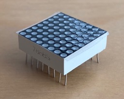
While physically a 16 row and 32 column design, it is logically organised as 8 rows and 64 columns. Logical row N drives physical rows N and N+8.
Uses a 3-pin header to drive a series of 74HC595 shift registers. First shift register is connected to a 74HC238 3-to-8 decoder to provide hardware enforced one-hot enable of rows. Rows are driven by a PMV16XN SMT power MOSFET to provide enough current to drive 32 LED columns.
Another eight 8-bit shift registers provide control over the 64 columns, with each column using a 680 ohm resistor to limit current. Brightness of individual LEDs can be supported externally by reprogramming the shift register and pulse-width-modulating the on-time for each column.
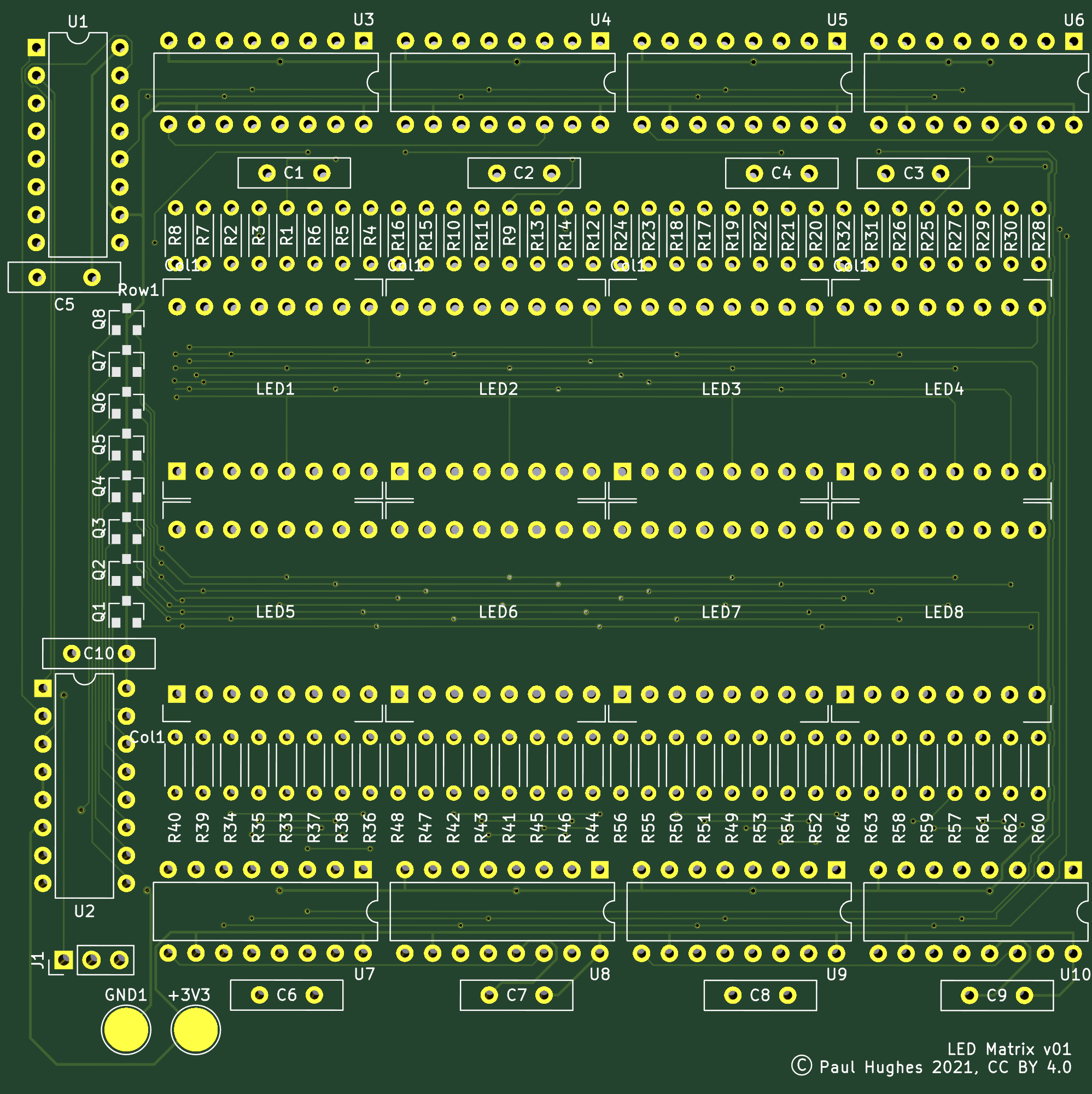
Board layout is intended for manufacture by PCB Way and follows PCB Way design rules. Please check compatibility with design rules for any other PCB house.
Board is a very basic design and intended for low frequency operation only. In particular there is no ground plane, which I plan to include in a future revision.
Take care with 788BS parts, I recommend testing them before soldering onto the board. The first board I've built has a short circuit inside one of 788BS components, are these are difficult to remove as the pins are underneath the package.
v01 of the board transposed rows 6 and 7 on the included 788BS symbol. This can be resolved by transposing the data for these rows in software before driving the serial interface.
I plan to release C drivers for Paspberry Pi Pico. Eventually I plan to migrate the IO the Pico's programmable IO.
| Qty | Value | Footprint | References |
|---|---|---|---|
| 64 | 680 | Resistor_THT:R_Axial_DIN0204_L3.6mm_D1.6mm_P5.08mm_Horizontal | R1, R2, R10, R11, R12, R13, R14, R15, R16, R17, R18, R19, R20, R21, R22, R23 +48 |
| 10 | 100nF | Capacitor_THT:C_Disc_D10.0mm_W2.5mm_P5.00mm | C1, C2, C3, C4, C5, C6, C7, C8, C9, C10 |
| 9 | 74HC595 | Package_DIP:DIP-16_W7.62mm | U1, U3, U4, U5, U6, U7, U8, U9, U10 |
| 8 | PMV16XN | Package_TO_SOT_SMD:SOT-23 | Q1, Q2, Q3, Q4, Q5, Q6, Q7, Q8 |
| 1 | +3V3 | TestPoint:TestPoint_Pad_D4.0mm | +3V3 |
| 1 | 74HC238 | Package_DIP:DIP-16_W7.62mm | U2 |
| 1 | GND | TestPoint:TestPoint_Pad_D4.0mm | GND1 |
| 1 | Header_01x03 | Connector_PinHeader_2.54mm:PinHeader_1x03_P2.54mm_Vertical | J1 |
| 1 | LED8x8_R1C1 | first:788BS | LED1 |
| 1 | LED8x8_R1C2 | first:788BS | LED2 |
| 1 | LED8x8_R1C3 | first:788BS | LED3 |
| 1 | LED8x8_R1C4 | first:788BS | LED4 |
| 1 | LED8x8_R2C1 | first:788BS | LED5 |
| 1 | LED8x8_R2C2 | first:788BS | LED6 |
| 1 | LED8x8_R2C3 | first:788BS | LED7 |
| 1 | LED8x8_R2C4 | first:788BS | LED8 |
It measures 100 × 100 mm and has 2 copper layers, 1.6 mm thick.
103 parts, built around the 74HC595, 74HC238D and PMV16XNR. The full list of its parts is on this page, with links to each part's symbol and footprint where PCBKit's library has them.
From the ph37/led_matrix_pcb repository on GitHub, at the commit this page was made from: the board is kicad/led_matrix_pcb.kicad_pcb. PCBKit opens the board in the browser, with nothing to install.
Its repository states no licence, so its author keeps all rights: ask ph37 before reusing the design.

Peppson/water-leak-sms-alarm
Small battery powered device that detects water leakage and sends an SMS alert

spel-uchile/balloon_experiment
Radiosonde platform to develop, test and integrate payloads for the future CubeSats missions


LeHack/SPSP
Particulate matter pollution monitoring system (:poland: System Pomiaru Stężenia Pyłu w powietrzu)


stonedDiscord/Automatenplatinen
Reverse engineerte Hardware aus deutschen Spielautomaten.

john0312/hitcon-pcb-badge
execute fw/merge.py to merge STM32CubeIDE generated main.c with user code in main.cc into main.cc.