4 layers60 × 60 mm
Stillpoint
techmiguel/stillpoint
Open-hardware 60 GHz radar ceiling sensor: presence & fall detection without a camera. Matter over Thread, KiCad 4-layer Ø60 mm board.
95 parts1CERN-OHL-S-2.0

 Person-0/Cmote
A USB-C IR transmitter built-in to a devboard powered by the Attiny1616 MCU
Cmote is an open-source printed circuit board by Person-0, from the Person-0/Cmote repository on GitHub. It is a 4-layer board of 21.2 × 30.6 mm with 20 parts on 31 nets, routed with 253 tracks and 27 vias.
It is built around the CH340N, IR16-213C/L510/TR8 and CC0402KRX5R7BB104, with the CC0402KRX5R7BB474, HYCW671-USBC14-115B and SI2302CDS-T1-GE3-ES among its other parts. Its parts include 5 capacitors, 5 connectors, 4 resistors, 3 ICs and 1 transistor. It belongs with the microcontroller boards boards and the AVR (ATmega, ATtiny) boards of this library.


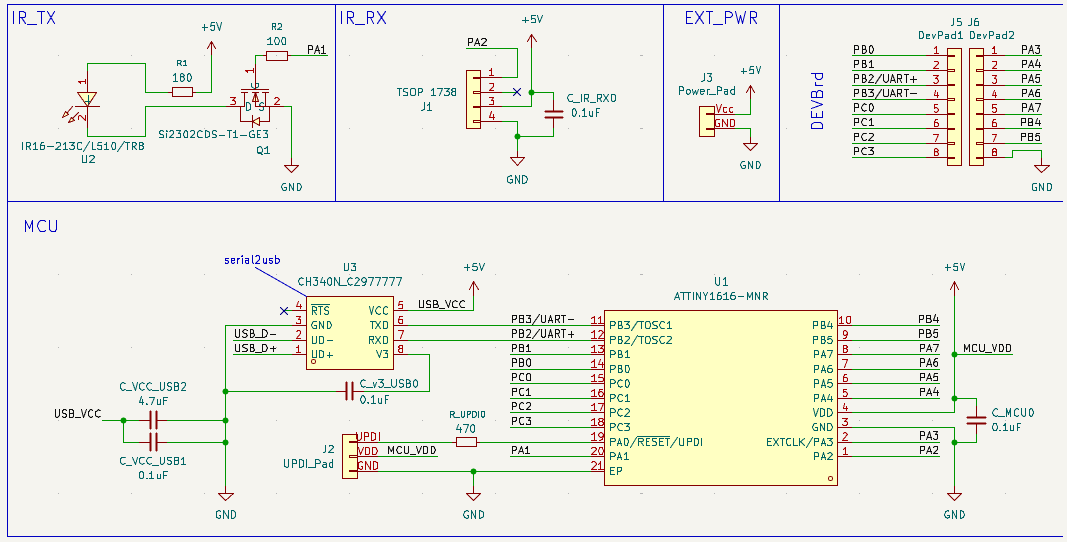
A USB-C IR transmitter for controlling devices like ACs, TVs for when you're too lazy to find the remote and your smartphone does not have a built-in IR blaster. Built-in to a devboard powered by the Attiny1616 MCU.
View PCB Directory: /PCB
Schematics:
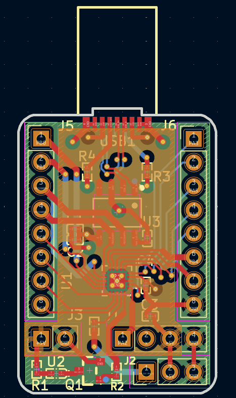
PCB:
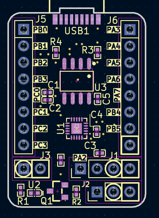
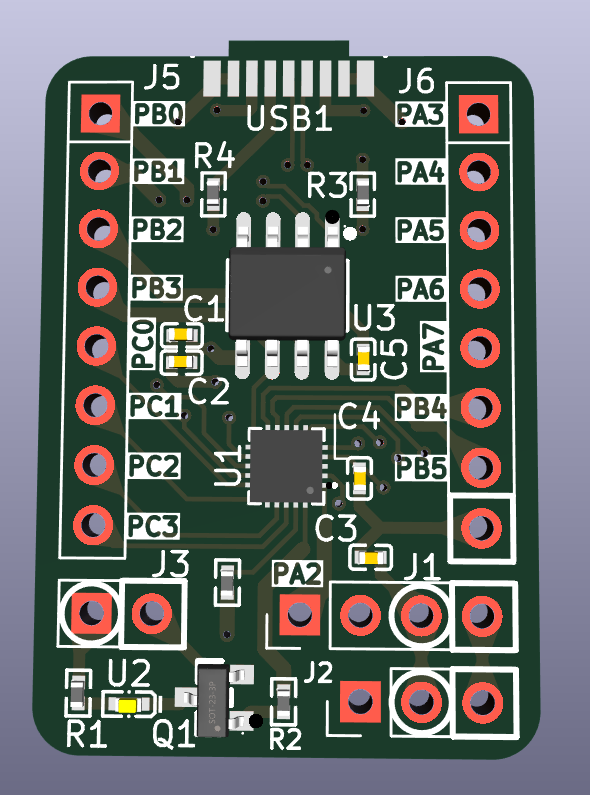
Preview PCB 3D View:
Steps to open the schematics and PCB files in KiCAD:
Cmote.kicad_proThis will open the schematics and PCB in KiCAD for easier viewing!
View firmware directory: /firmware
Note that firmware is Work In Progress. Until I physically receive the board I have no way of knowing whether this works or not so current it is just basic stuff.
The current firmware will send a power command at the start, listen to all the IR signals and print them to the serial on USB-C port of the board:
bool sentPwrCmd = false;

void setup() {
	Serial.begin(115200); // serial is on usb-c
	IrSender.begin(IR_TX_PIN);
	IrReceiver.begin(IR_RX_PIN, ENABLE_LED_FEEDBACK);
}

void loop() {

	if (!sentPwrCmd) {
		uint16_t address = 0x00; // standard device address
		uint8_t command = 0x45;  // standard power command
		IrSender.sendNEC(address, command, 0);
		sentPwrCmd = true;
		Serial.println("=== power command was sent!! ===");
	}

	if (IrReceiver.decode()) {
		Serial.println("-------------------------");
		Serial.println("\tbegin decode():");
        Serial.print("Protocol: ");
        Serial.println(getProtocolString(IrReceiver.decodedIRData.protocol));
Serial.print("Command (Hex): 0x");IrReceiver and IrSender is from the IRremote library.
As for flashing the firmware onto the board, it requires a specialized UPDI programmer. However, I will be using another devboard to program this using pyupdi. This guide will be updated after I test it myself to confirm what works and what does not.
View CAD Directory: /CAD
While this is technically a devboard and has no requirement for a case, I still made one using Fusion360.
It looks like this:
USB-C plug is invisible as no model was available for it from the manufacturer so I made sure to give enough space by measuring the silkscreen dimensions on the PCB and using it as the reference.
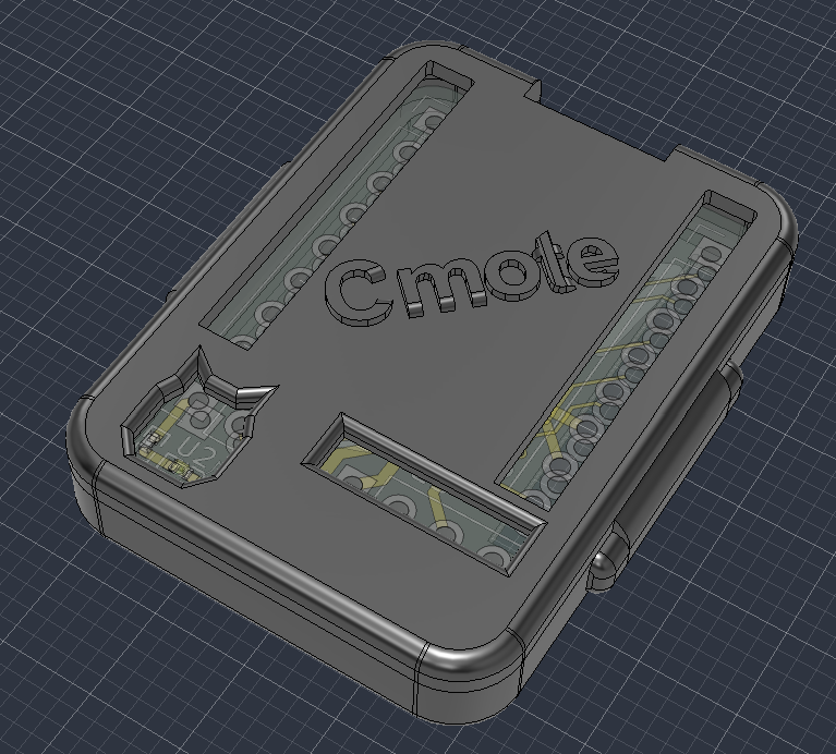
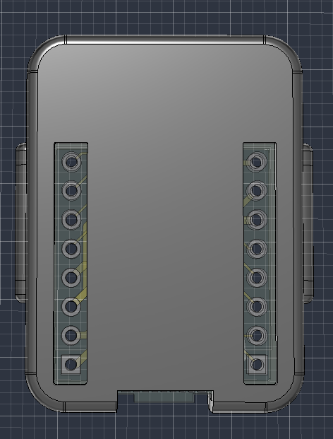
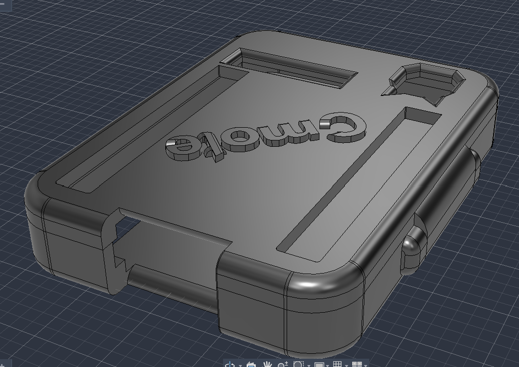
The lid will friction fit into the case using the side extrusions.
It has rectangular cuts for headers so the devboard can be freely used without taking off the lid again and again.
For 3d printing, files Cmote_body.step and Cmote_lid.step need to be printed as different bodies.
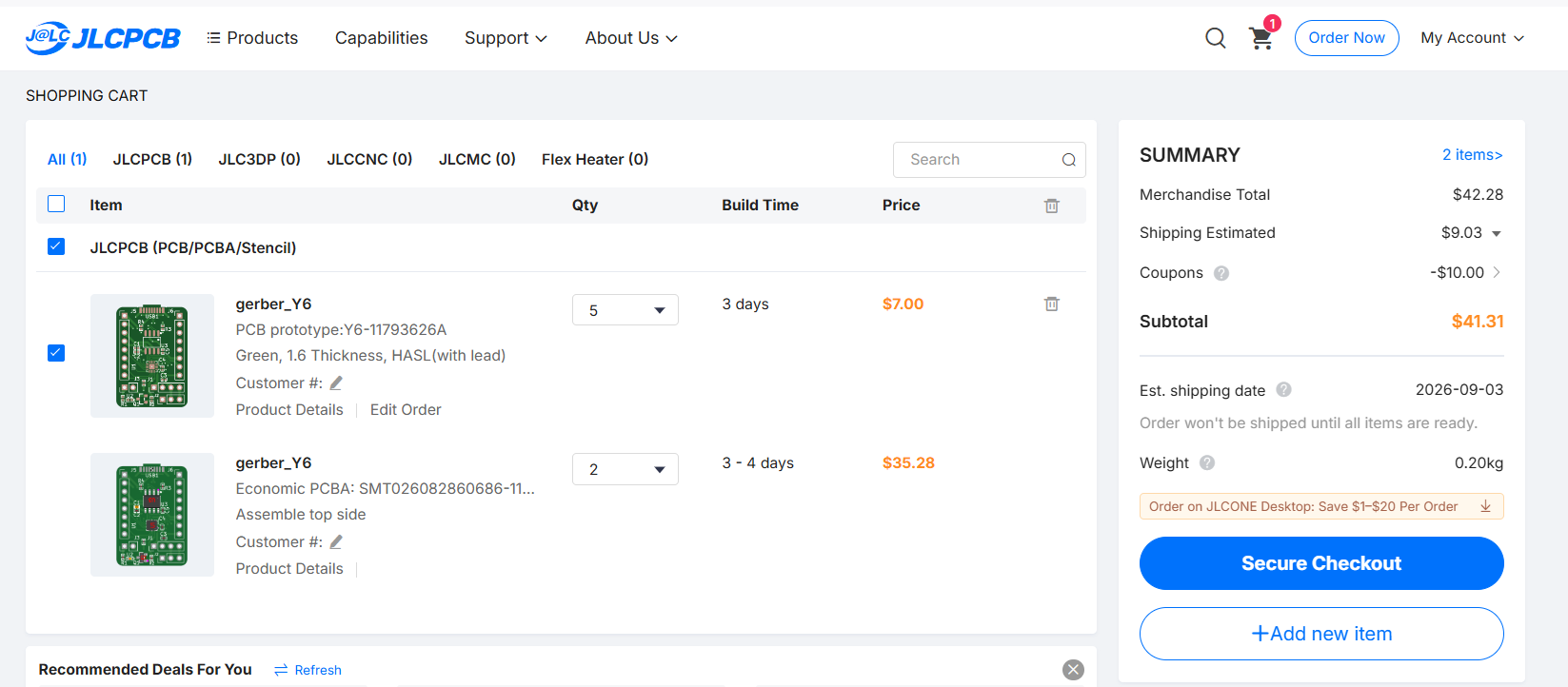
I will be using JLCPCB to order my PCB as for my location it is the cheapest option (if using PCB Assembly service).
Please checkout the JLC_Order directory for bom, cpl and gerber files.
The grand total for this project comes out to be at 42.24 USD
| Qty | Value | Footprint | References |
|---|---|---|---|
| 4 | 0.1uF | easyeda2kicad:C0402 | C2, C3, C4, C5 |
| 2 | 5.1k | easyeda2kicad:R0402 | R3, R4 |
| 1 | 100 | easyeda2kicad:R0402 | R2 |
| 1 | 180 | easyeda2kicad:R0402 | R1 |
| 1 | 4.7uF | easyeda2kicad:C0402 | C1 |
| 1 | 470 | easyeda2kicad:R0402 | R_UPDI0 |
| 1 | ATTINY1616-MNR | easyeda2kicad:QFN-20_L3.0-W3.0-P0.40-BL-EP1.7 | U1 |
| 1 | CH340N_C2977777 | easyeda2kicad:SOP-8_L4.9-W3.9-P1.27-LS6.0-BL | U3 |
| 1 | DevPad1 | Connector_PinHeader_2.54mm:PinHeader_1x08_P2.54mm_Vertical | J5 |
| 1 | DevPad2 | Connector_PinHeader_2.54mm:PinHeader_1x08_P2.54mm_Vertical | J6 |
| 1 | HYCW671-USBC14-115B | easyeda2kicad:USB-SMD_HYCW671-USBC14-115B | USB1 |
| 1 | IR16-213C/L510/TR8 | easyeda2kicad:LED0402-FD_YELLOW | U2 |
| 1 | Power_Pad | Connector_PinHeader_2.54mm:PinHeader_1x02_P2.54mm_Vertical | J3 |
| 1 | Si2302CDS-T1-GE3 | easyeda2kicad:SOT-23_L2.9-W1.3-P1.90-LS2.4-BR | Q1 |
| 1 | TSOP 1738 | Connector_PinHeader_2.54mm:PinHeader_1x04_P2.54mm_Vertical | J1 |
| 1 | UPDI_Pad | Connector_PinHeader_2.54mm:PinHeader_1x03_P2.54mm_Vertical | J2 |
It measures 21.2 × 30.6 mm and has 4 copper layers, 1.6 mm thick.
20 parts, built around the CH340N, IR16-213C/L510/TR8, CC0402KRX5R7BB104 and CC0402KRX5R7BB474. The full list of its parts is on this page, with links to each part's symbol and footprint where PCBKit's library has them.
From the Person-0/Cmote repository on GitHub, at the commit this page was made from: the board is PCB/Cmote/Cmote.kicad_pcb and its schematic PCB/Cmote/Cmote.kicad_sch. PCBKit opens the board in the browser, with nothing to install.
Its repository states no licence, so its author keeps all rights: ask Person-0 before reusing the design.
techmiguel/stillpoint
Open-hardware 60 GHz radar ceiling sensor: presence & fall detection without a camera. Matter over Thread, KiCad 4-layer Ø60 mm board.

MicroType-Engineering/MTE_USB_HUB
As designed on the MicroType Engineering's YouTube series: https://youtu.be/uzqXgHHZUUs

EnAccess/Cicada-WiSUN-HW
IoT Communications Module for Energy Access. A quick way to get production ready, bi-directional communications for your IoT embedded device.

NessieCircuits/Riotee_Board
The Riotee board is a development board for battery-free wireless devices. The on-board wireless microcontroller runs off energy harvested from, for example, a solar panel and uses only tiny capacitors as energy…

sushrutchhatkuli/Custom-ESP32-drone-PCB
Designed a custom ESP32-WROOM-32–based drone flight controller PCB featuring USB-C charging, regulated 3.3 V power delivery, and onboard IMU sensing using the MPU-6050.

c-m-w/deal-cards-public
A robot that deals playing cards to multiple players around a table. A single central motor rotates the whole mechanism to aim at each player in turn, a brushless motor launches the card, and a closed-loop sensor…

claudiofin/smartbag
Tagless smart insert for a handbag: recognises its contents with an IR camera, 60 GHz radar and a 96-taxel FSR floor. PCB, CAD, renders and films all generated by script (KiCad -> CadQuery -> Blender).
