2 layers54 × 29 mm
Sonos magic hub
perja12/sonos_magic_hub
Circuit for using the LG OLED C9 TV remote (LG Magic Remote) with the Sonos Playbar.
18 parts3Apache-2.0

 perja12/roomba_beacon
IR beacon that can be used to limit where the Roomba vacuum cleaner goes.
Ir beacon is an open-source printed circuit board by perja12, from the perja12/roomba_beacon repository on GitHub, published under the MIT licence. It is a 2-layer board of 79.4 × 49.1 mm with 20 parts on 12 nets, routed with 102 tracks and 7 vias.
It is built around the ATTINY85V-10SU and MMBT3904. Its parts include 4 resistors, 3 capacitors, 2 diodes, 2 switches and 1 IC. It belongs with the AVR (ATmega, ATtiny) boards of this library.


Quick links: Schematic | Interactive BOM
This project describes an IR beacon that can be used with certain Roomba vacuum cleaners. The beacon can be used to prevent the vacuum cleaner from entering a room or other off-limit zones. The vacuum cleaner will simply turn around when it receives the infrared light emitted from the beacon.
The project is inspired by a similar project from http://gregthielen.me/blogstuff/2017/06/27/roomba-virtual-wall/ and the timings for IR LED is taken directly from that page.
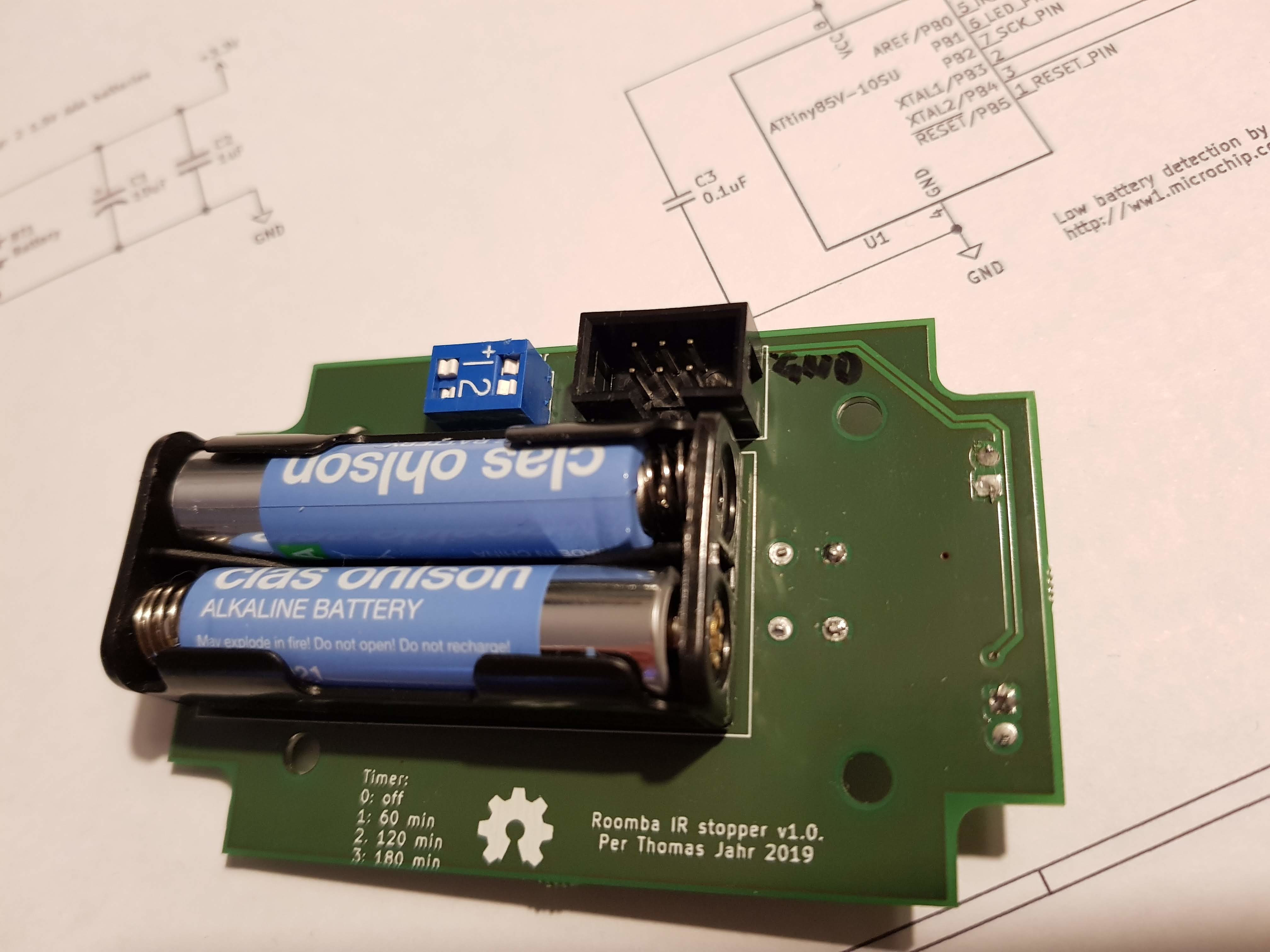
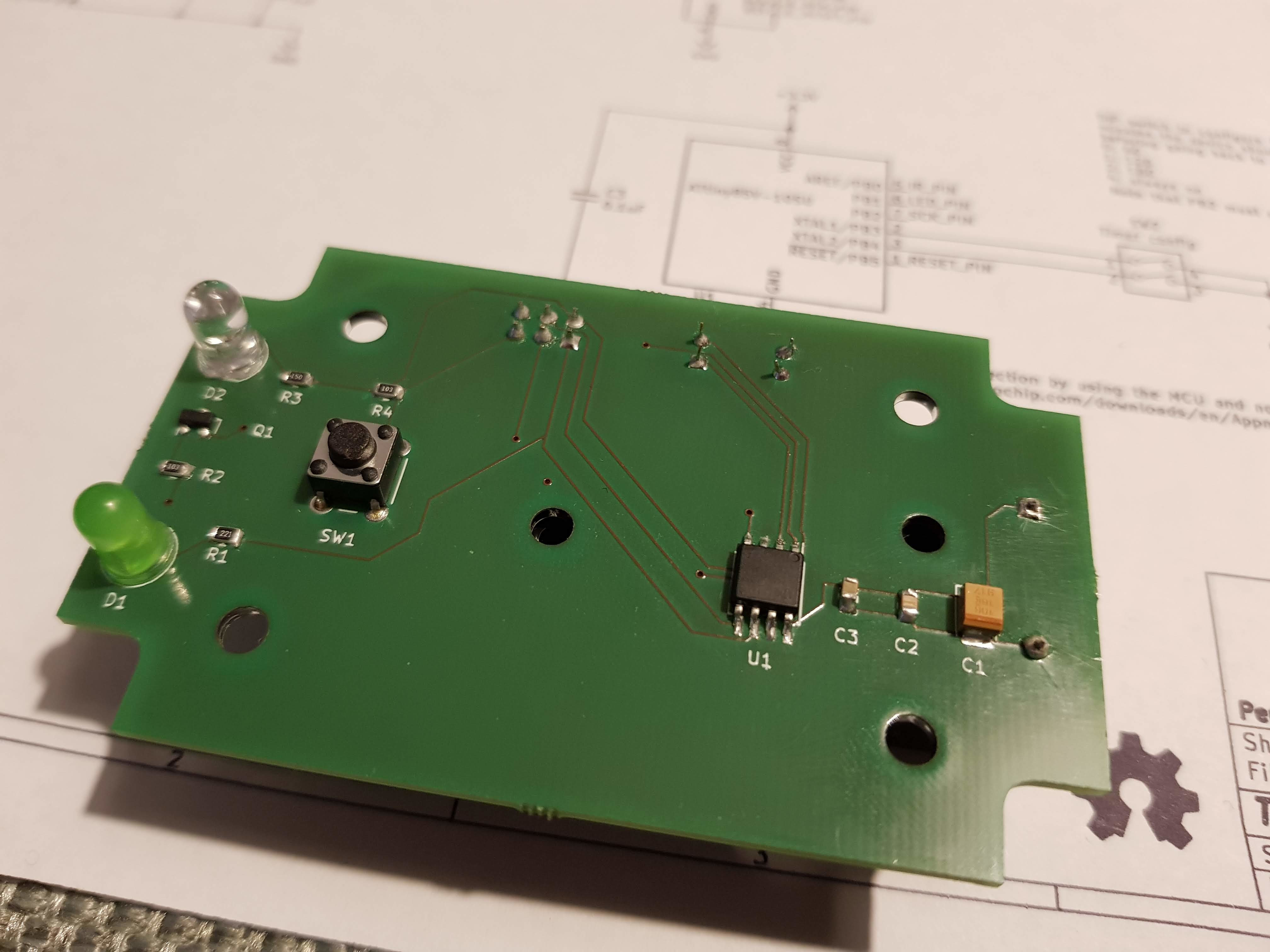
The circuit itself is simple enough; when the push button is pressed, the IR LED will flash in a given pattern. To save battery the duration is limited to one hour (configurable). In addition there is a green indicator LED that will flash once when the device is turned on and twice when turned off.
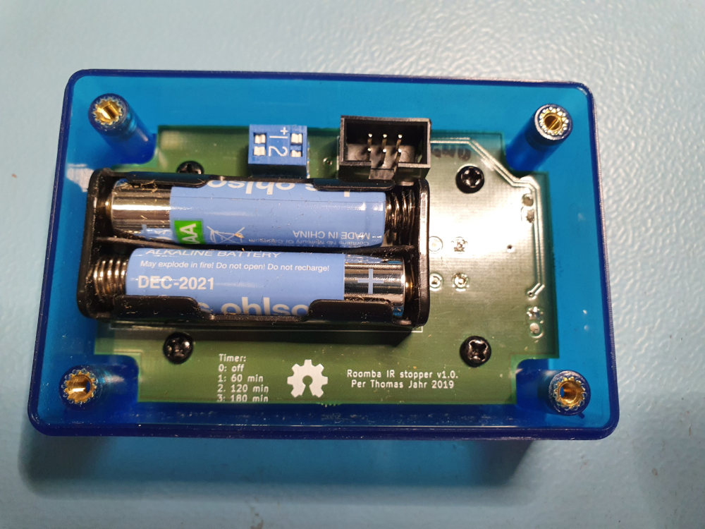
An ATtiny85V is used without any voltage regulator as it can operate with a voltage from 1.8 to 5.5V. The device is powered by two AAA alkaline batteries and the battery holder is soldered to the PCB. As the ATtiny85 have maximum current of 40 mA per pin and the IR LED (Vishay TSAL4000) has a forward current of 100 mA, we will need a transistor (MMBT3904) to switch the IR LED.
There are two modes of operation:
Sleep mode: the IR LED is off and the MCU is in deep sleep. The current consumption is a couple of uA.
The average current consumption during active mode (when blinking the IR LED) is about 3.3 mA and can be lowered by using SLEEP_IDLE to save power and wake up when 132 ms have passed.
The circuit uses a power latch implemented by using special instructions that skips resetting a particular variable to zero during reset (see the power variable in the code). The push button is connected to the RESET pin and when pressed it will reset the MCU. The setup function toggles the power variable and the circuit either goes to sleep or starts blinking the LED. With such a design it is important to have low sleep current. The solution is described here: http://www.technoblogy.com/show?VOO.
Depending on the route the vacuum cleaner chooses one can decide how many hours the device will be on. The user can configure this by setting two DIP switches. The duration is measured by using the number of milliseconds since the device was reset. The accuracy of this timer is not very good and can be off by several minutes. But for this purpose it works well enough.
On start up the indicator LED will blink rapidly if it is time to replace the batteries (around 2V). This is implemented by setting the internal reference voltage as ADC input and the target VCC as the ADC reference. The solution is described in this application note from Microchip: http://ww1.microchip.com/downloads/en/Appnotes/00002447A.pdf
Install the ATTinyCore and use the following settings in the Arduino IDE
There is also a Makefile that uses arduino-cli.
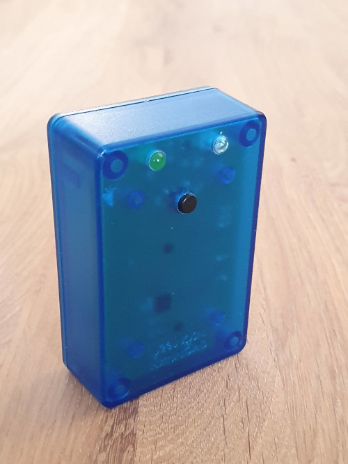
The PCB is designed so that it fits the Hammond 1591 ABS multipurpose enclosure and can be mounted directly without any standoffs. Only three additional holes are needed. Using one of the transparent boxes makes it easy to see where to drill. Note that there is a slight angle on the sides so the box wont stand exactly at 90 degrees, but close enough.
List of improvements that can be done:
| Qty | Value | Footprint | References |
|---|---|---|---|
| 2 | 10K | Resistor_SMD:R_0805_2012Metric | R2, R4 |
| 1 | 0.1uF | Capacitor_SMD:C_0805_2012Metric | C3 |
| 1 | 10uF | Capacitor_Tantalum_SMD:CP_EIA-6032-28_Kemet-C_Pad2.25x2.35mm_HandSolder | C1 |
| 1 | 15 | Resistor_SMD:R_0805_2012Metric | R3 |
| 1 | 1uF | Capacitor_SMD:C_0805_2012Metric | C2 |
| 1 | 220 | Resistor_SMD:R_0805_2012Metric | R1 |
| 1 | ATtiny85V-10SU | Package_SO:SOIJ-8_5.3x5.3mm_P1.27mm | U1 |
| 1 | AVR-ISP-6 | Connector_IDC:IDC-Header_2x03_P2.54mm_Vertical | J1 |
| 1 | Battery | Battery:BatteryHolder_Keystone_2468_2xAAA | BT1 |
| 1 | CQY99 | LED_THT:LED_D5.0mm_IRGrey | D2 |
| 1 | LED | LED_THT:LED_D5.0mm | D1 |
| 1 | MMBT3904 | Package_TO_SOT_SMD:SOT-23 | Q1 |
| 1 | On/off | Button_Switch_THT:SW_PUSH_6mm | SW1 |
| 1 | Timer config | Button_Switch_THT:SW_DIP_SPSTx02_Slide_9.78x7.26mm_W7.62mm_P2.54mm | SW2 |
The 15 most common of 20 parts.
perja12/sonos_magic_hub
Circuit for using the LG OLED C9 TV remote (LG Magic Remote) with the Sonos Playbar.

mjrskiles/gatekeeper
A digital gate/trigger processor for Eurorack modular synthesizers. Gatekeeper has a two-state (0 or 5V) output driven by push button and CV input. The input response is configurable via menu settings.

IvDm/Z-probe-on-smd-resistors-2512
Auto bed level strain gage for 3D printer using resistors 2512 instead of strain gauges.

MouseBiteLabs/Super-Game-Boy-Plus
A replacement circuit board for improving the Super Game Boy, or for creating a standalone Game Boy game for the SNES.

joelsernamoreno/Attiny85-Standalone
PCB designs based on the Attiny85 microcontroller for standalone development.

hzeller/digi-spherometer
A digital spherometer, reading data from digital dial indicator and converting it to radius, displaying on OLED display.


rjhsun/moleblink
ATtiny85-based illuminated PCB keychain featuring the Blacker House crest
It measures 79.4 × 49.1 mm and has 2 copper layers, 1.6 mm thick.
20 parts, built around the ATTINY85V-10SU and MMBT3904. The full list of its parts is on this page, with links to each part's symbol and footprint where PCBKit's library has them.
From the perja12/roomba_beacon repository on GitHub, at the commit this page was made from: the board is kicad/ir_beacon/ir_beacon.kicad_pcb and its schematic kicad/ir_beacon/ir_beacon.kicad_sch. PCBKit opens the board in the browser, with nothing to install.
Its repository publishes it under the MIT licence: you may reuse it on that licence's terms (keep the author's notice, and for a copyleft licence share your changes alike).