2 layers39 × 71 mm

 perc-sw/analog_shield
CAD files for the student workshop Analog Shield board.
Analog shield is an open-source printed circuit board by perc-sw, from the perc-sw/analog_shield repository on GitHub, published under the GPL-3.0 licence. It is a 4-layer board of 68.6 × 53.3 mm with 49 parts on 48 nets, routed with 189 tracks and 4 vias.
It is built around the LMT84LPM, TLV2472AIP and PEC11L-4220F-S0015, with the PPTC062LFBN-RC and S3B-EH(LF)(SN) among its other parts. Its parts include 18 resistors, 8 capacitors, 7 connectors, 3 diodes and 2 ICs.


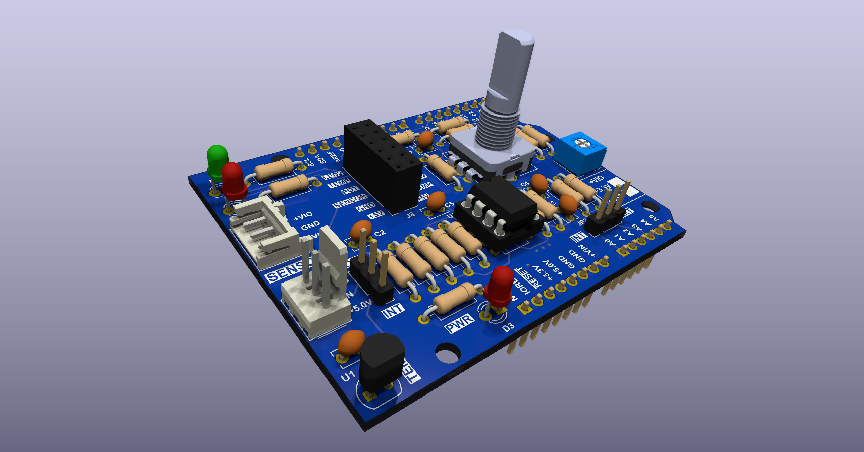
This repository has all CAD files for the Analog Shield board used in the University of Toronto, Department of Physic, "Introduction to Electronics course."
This board is used to train graduate students first and foremost in through hole solder techniques. As part of the training in the course they will as learn analog front end, digital IO design methods as well. Other than a teaching aid there is not intended practical use for this board.
The CAD program used to design this board is KiCAD which open source and free to use. The Interactive Html BoM plugin was used to generate the interactive bill of materials html file.
| Qty | Value | Footprint | References |
|---|---|---|---|
| 6 | 4.7K | analog_front_end:R_Axial_DIN0207_L6.3mm_D2.5mm_P10.16mm_Horizontal | R7, R8, R9, R16, R17, R18 |
| 5 | 10K | analog_front_end:R_Axial_DIN0207_L6.3mm_D2.5mm_P10.16mm_Horizontal | R3, R5, R6, R13, R14 |
| 4 | MountingHole | analog_front_end:MountingHole_3.2mm_M3 | H1, H2, H3, H4 |
| 3 | 10000pF | analog_front_end:C_Disc_D3.8mm_W2.6mm_P2.50mm | C6, C7, C8 |
| 3 | 1K | analog_front_end:R_Axial_DIN0207_L6.3mm_D2.5mm_P10.16mm_Horizontal | R10, R11, R12 |
| 2 | 0.1µF | analog_front_end:C_Disc_D3.8mm_W2.6mm_P2.50mm | C1, C5 |
| 2 | Conn_01x08 | analog_front_end:PinHeader_1x08_P2.54mm_Vertical | J3, J7 |
| 2 | Jumper_3_Open | analog_front_end:SolderJumper-3_P2.0mm_Open_TrianglePad1.0x1.5mm | JP3, JP4 |
| 2 | RED | analog_front_end:LED_D3.0mm | D2, D3 |
| 1 | 1000pF | analog_front_end:C_Disc_D3.8mm_W2.6mm_P2.50mm | C4 |
| 1 | 10K | analog_front_end:TRIM_3362P-1-103LF | RV1 |
| 1 | 16.9K | analog_front_end:R_Axial_DIN0207_L6.3mm_D2.5mm_P10.16mm_Horizontal | R1 |
| 1 | 1µF | analog_front_end:C_Disc_D3.8mm_W2.6mm_P2.50mm | C2 |
| 1 | 2200pF | analog_front_end:C_Disc_D3.8mm_W2.6mm_P2.50mm | C3 |
| 1 | 35.7K | analog_front_end:R_Axial_DIN0207_L6.3mm_D2.5mm_P10.16mm_Horizontal | R4 |
| 1 | 6.98K | analog_front_end:R_Axial_DIN0207_L6.3mm_D2.5mm_P10.16mm_Horizontal | R15 |
| 1 | 640456-3 | analog_front_end:Molex_KK-254_AE-6410-03A_1x03_P2.54mm_Vertical | J1 |
| 1 | 680 | analog_front_end:R_Axial_DIN0207_L6.3mm_D2.5mm_P10.16mm_Horizontal | R2 |
| 1 | Conn_01x06 | analog_front_end:PinHeader_1x06_P2.54mm_Vertical | J4 |
| 1 | Conn_01x10 | analog_front_end:PinHeader_1x10_P2.54mm_Vertical | J6 |
| 1 | GREEN | analog_front_end:LED_D3.0mm | D1 |
| 1 | Jumper_3_Bridged12 | analog_front_end:PinHeader_1x03_P2.54mm_Vertical | JP1 |
| 1 | Jumper_3_Open | analog_front_end:PinHeader_1x03_P2.54mm_Vertical | JP2 |
| 1 | LMT84LPM | analog_front_end:TO-92 | U1 |
| 1 | PEC11L-4220F-S0015 | analog_front_end:RotaryEncoder_Alps_EC12E-Switch_Vertical_H20mm_CircularMountingHoles | ENC1 |
| 1 | PPTC062LFBN-RC | analog_front_end:PinSocket_2x06_P2.54mm_Vertical | J8 |
| 1 | S3B-EH(LF)(SN) | analog_front_end:JST_EH_S3B-EH_1x03_P2.50mm_Horizontal | J2 |
| 1 | TLV2472AIP | analog_front_end:DIP-8_W7.62mm | U2 |
The 48 most common of 49 parts.

Laracleteuh/projet-tank-terminale-2026-2027
Repo GitHub pour le projet de Tank RC des Terminales spécialités sciences de l'ingénieur. Contenu Open - Source, et maintenu jusqu'en juillet 2027

mvirkkunen/encodering
encodering (unfinished - the firmware for one has never even been run) ======================================================================


ldcyes/OpenDuck
已完成可编辑原理图、真实四层 PCB 和本地库。阶梯板面积 4510 mm²,比原 65×60 + 32×30 mm 两板总面积 4860 mm² 少 350 mm²(7.20%)。原 TDK 模块本体、四个安装孔和原 TDK 器件位置保留,回生电容采用原料号卧装,J1 因实际拔插通道冲突改为同系列 BM08 顶插。当前为工程候选,未制造,未完成热、回生瞬态、低电量或行走验收。


hackclub/OnBoard
💡 Join 1,000 teenagers and make your first PCB with a $100 grant!

It measures 68.6 × 53.3 mm and has 4 copper layers, 1.6 mm thick.
49 parts, built around the LMT84LPM, TLV2472AIP, PEC11L-4220F-S0015 and PPTC062LFBN-RC. The full list of its parts is on this page, with links to each part's symbol and footprint where PCBKit's library has them.
From the perc-sw/analog_shield repository on GitHub, at the commit this page was made from: the board is analog_shield.kicad_pcb and its schematic analog_shield.kicad_sch. PCBKit opens the board in the browser, with nothing to install.
Its repository publishes it under the GPL-3.0 licence: you may reuse it on that licence's terms (keep the author's notice, and for a copyleft licence share your changes alike).