
2 layers68.8 × 53.6 mm
ZArduino
zmaker/arduino_cookbook
gli sketch del nuovo progetto Arduino Cookbook e dei video di YouTube
46 parts269

 PegLegDino/Roku_IR_Controller1
This is a literally just an infrared remote, might add a youtube video later.
Serial programmer is an open-source printed circuit board by PegLegDino, from the PegLegDino/Roku_IR_Controller repository on GitHub, published under the MIT licence. It is a 2-layer board of 58.4 × 61 mm with 22 parts on 30 nets, routed with 157 tracks and 0 vias.
It is built around the ATMEGA328P-PU. Its parts include 6 connectors, 5 capacitors, 3 resistors, 3 diodes and 2 ICs. It belongs with the interfaces and adapters boards and the AVR (ATmega, ATtiny) boards of this library.
This is a controller for the Roku This software will provide you with both a template for sending and reciving IR signals as well as an example of the functional controller
I made this at 1AM so if none of this makes sense, I would be glad to answer questions you have in the issues tab...
When your run the reciever script and click your remote at it you'll get a code, the last 4 represent the user while the first 4 represent the data being sent. It'll look like this in the serial monitor...that is your code, use it to change mine.

Each roku is different so a little fiddling may be required.
In Short just take the raw data from your remote signal and replace the last four characters of my user data with yours in this script
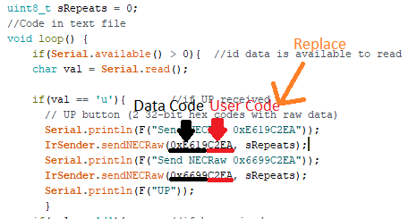
OOOOOOOOOH LOOK A SCHEMATIC...wow
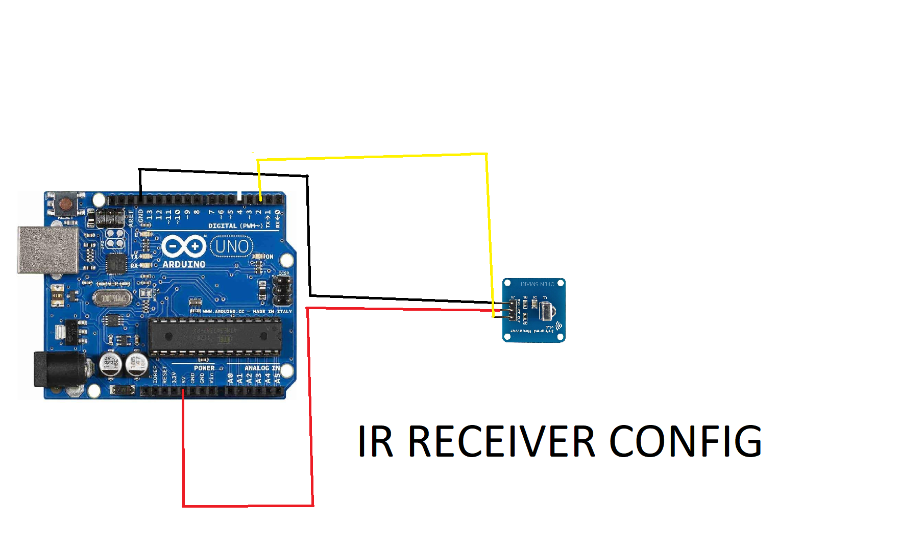 BOOM ANOTHER ONE (Update, I meant Transmitter)
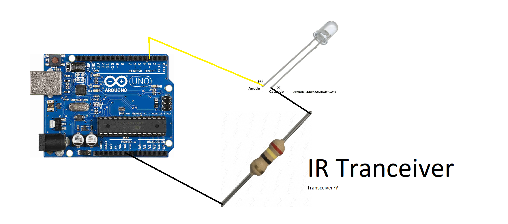 NOW JUST THE ENGINEERS...if you get this you deserve a cookie it's just an atmega328p serial programming circuit
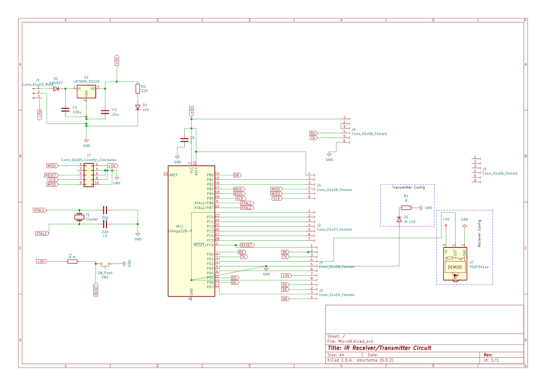 BONUS PCB DESIGN (For those whomst wish to be extra)
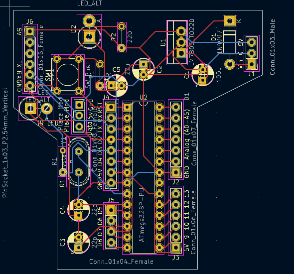
I don't make changes I make genius
*Added first stuff 4/25/2022
*Revised that stuff 4/25/2022
*Remebered I left out a lot of stuff 4/25/2022 (but later)
| Qty | Value | Footprint | References |
|---|---|---|---|
| 2 | 22p | Capacitor_THT:CP_Radial_D5.0mm_P2.50mm | C3, C4 |
| 2 | Conn_01x06_Female | Connector_PinHeader_2.54mm:PinHeader_1x06_P2.54mm_Vertical | J3, J6 |
| 2 | LED_ALT | Diode_THT:D_DO-201_P3.81mm_Vertical_AnodeUp | D2, IR LED |
| 2 | R | Resistor_THT:R_Axial_DIN0204_L3.6mm_D1.6mm_P5.08mm_Vertical | R1, R1 |
| 1 | 100u | Capacitor_THT:CP_Radial_D5.0mm_P2.50mm | C1 |
| 1 | 1N4007 | Diode_THT:D_DO-41_SOD81_P10.16mm_Horizontal | D1 |
| 1 | 220 | Resistor_THT:R_Axial_DIN0204_L3.6mm_D1.6mm_P5.08mm_Vertical | R2 |
| 1 | 22u | Capacitor_THT:CP_Radial_D5.0mm_P2.50mm | C2 |
| 1 | ATmega328P-PU | Package_DIP:DIP-28_W7.62mm | U2 |
| 1 | C | Capacitor_THT:CP_Radial_D5.0mm_P2.50mm | C5 |
| 1 | Conn_01x03_Male | Connector_PinHeader_2.54mm:PinHeader_1x03_P2.54mm_Vertical | J1 |
| 1 | Conn_01x04_Female | Connector_PinHeader_2.54mm:PinHeader_1x04_P2.54mm_Vertical | J5 |
| 1 | Conn_01x07_Female | Connector_PinHeader_2.54mm:PinHeader_1x07_P2.54mm_Vertical | J2 |
| 1 | Conn_01x08_Female | Connector_PinHeader_2.54mm:PinHeader_1x08_P2.54mm_Vertical | J4 |
| 1 | Crystal | Crystal:Crystal_HC49-U_Vertical | Y1 |
| 1 | LM7805_TO220 | Package_TO_SOT_THT:TO-220-3_Vertical | U1 |
| 1 | PinSocket_1x03_P2.54mm_Vertical | Connector_PinSocket_2.54mm:PinSocket_1x03_P2.54mm_Vertical | Place Mod |
| 1 | SW_Push | Button_Switch_THT:SW_Tactile_Straight_KSA0Axx1LFTR | SW1 |
zmaker/arduino_cookbook
gli sketch del nuovo progetto Arduino Cookbook e dei video di YouTube

coseyfannitutti/discipad
17-key numpad assembled with only through hole components, including usb type-c

matthewcieplak/super-sixteen
Code and schematics for the Super Sixteen Eurorack sequencer

coseyfannitutti/romeo
Staggered 40% keyboard pcb that can be assembled with only through hole components, including USB Type-C

mattybrad/drumkid
Version 4 was the first successful working design, with full code, schematics, Gerbers, etc available on GitHub.


leomil72/LM80C
A Z80-based homebrew computer withTMS9918, AY-3-8910, Z80 CTC, Z80 PIO, and Z80 SIO

It measures 58.4 × 61 mm and has 2 copper layers, 1.6 mm thick.
22 parts, built around the ATMEGA328P-PU. The full list of its parts is on this page, with links to each part's symbol and footprint where PCBKit's library has them.
From the PegLegDino/Roku_IR_Controller repository on GitHub, at the commit this page was made from: the board is Ki cad stuff/Serial programmer.kicad_pcb and its schematic Ki cad stuff/Serial programmer.kicad_sch. PCBKit opens the board in the browser, with nothing to install.
Its repository publishes it under the MIT licence: you may reuse it on that licence's terms (keep the author's notice, and for a copyleft licence share your changes alike).