2 layers45 × 100 mm
Walkiepcb
houseofthe051010/ESP32-Walkie-Talkie-V2
This ESP32 Walkie Talkie is redesigned with a SX1262 radio, a PCB, and a full case redesign.
93 parts1

 path321/sound_spectrum_mcu
STM32-powered board to analyze sound from MEMS microphone
Sound spectrum v1 is an open-source printed circuit board by path321, from the path321/sound_spectrum_mcu repository on GitHub, published under the MIT licence. It is a 4-layer board of 85.6 × 54 mm with 40 parts on 49 nets, routed with 410 tracks and 74 vias.
It is built around the ICS-43432, AP2112K-3.3 and USBLC6-2SC6, with the ABMM2-24.000MHZ-E2-T among its other parts. Its parts include 16 capacitors, 6 resistors, 5 ICs, 3 connectors and 2 diodes. It belongs with the audio and music and sensors and measurement boards and the STM32 boards of this library.


STM32-powered board for analyzing sound input from MEMS microphones, designed as an open-source, hands-on introduction to DSP on ARM Cortex-M4 processors.
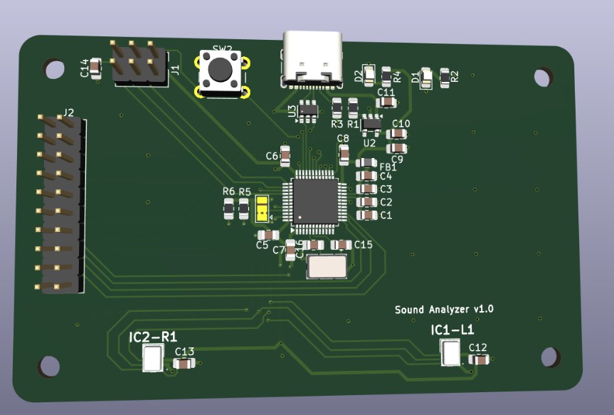
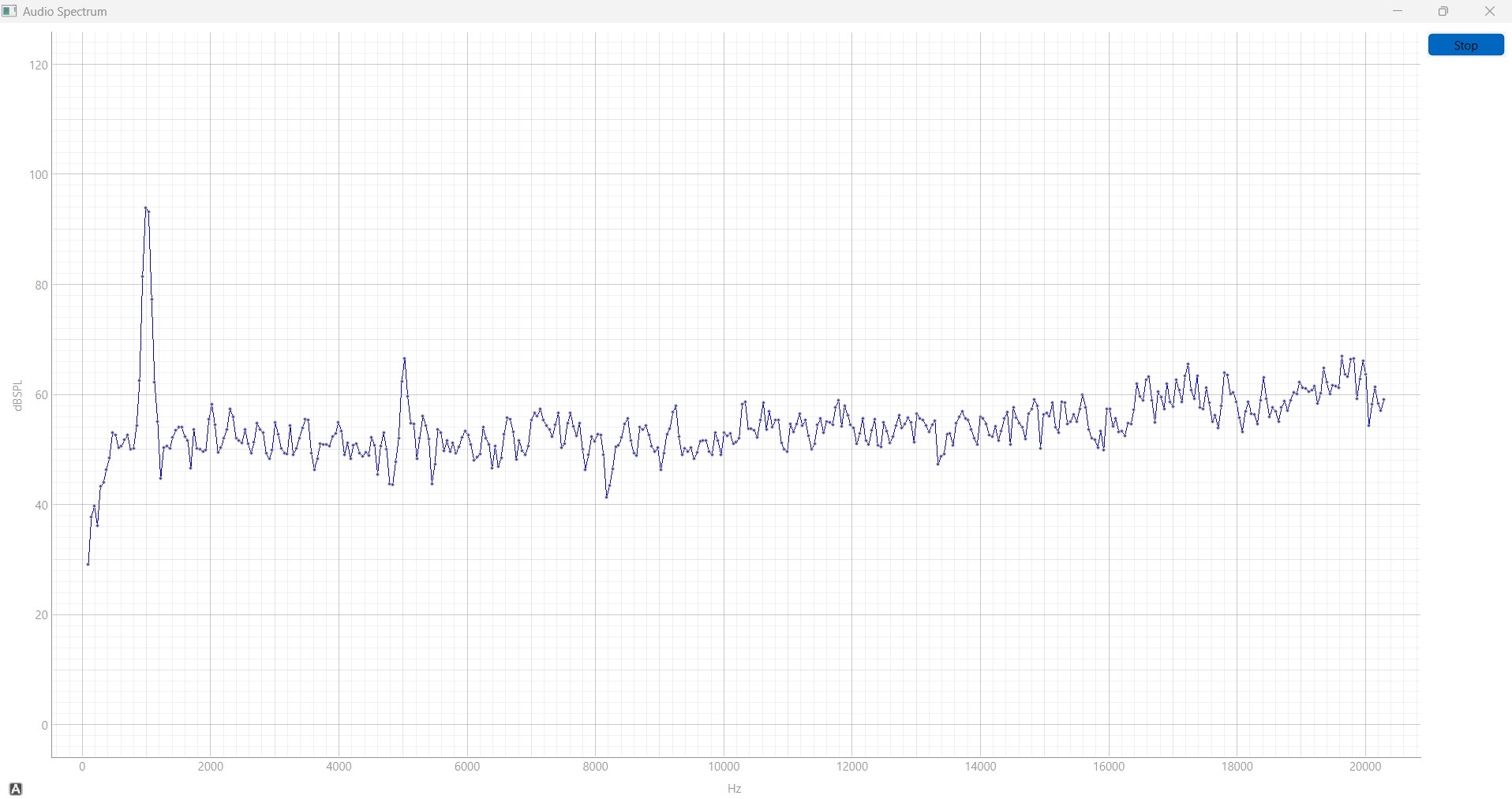
It uses the CMSIS-DSP library to handle computationally intensive tasks, while a companion PyQt-based Python script is used for plotting frequency-domain data data from PCB to host PC.
The goal is to demonstrate the full pipeline of audio signal acquisition and transformation, from raw time-domain data to frequency-domain analysis
The PCB intentionally exposes additional unused pins, allowing users to extend functionality and experiment beyond the core features
1kHz sine
| Front | Back |
|---|---|
 |  |
In progress, working version availabe in main branch
Full STM32CubeIDE project is hosted here, with .elf and .bin files ready inside code/sound_analyzer_v1/Debug folder
As for python script, both source plot_graph.py and executable plot_graph.exe are available, with executable tested only for Windows platform
For application usage, no extra programm shall be installed , other than downloading the executable plot_graph.exe
For developer usage, STM32CubeIDE + STM32CubeMX shall be installed, as described here
In addition, Python >=3.9 shall be installed from here, with the following Python libraries also installed :
PCB files are located on pcb/ folder, while device files can be found on code/sound_analyzer_v1/ and plot files on code/plot_graph/
This project is hosted on GitHub. You can clone this project directly using this command:
https://github.com/path321/sound_spectrum_mcu.gitConnect the board via USB to your host PC. Make sure that no other STM32-based USB is connected to PC
Unzip plot_graph.zip Double click on plot_graph.exe
If you want to stop the live graph, check on the Button on the top right end of the GUI window
This project uses Semantic Versioning. For a list of available versions, see the repository tag list.
Please create a new issue on
https://github.com/path321/sound_spectrum_mcu/issues
This project is licensed under the MIT License - see LICENSE.md file for details.
| Qty | Value | Footprint | References |
|---|---|---|---|
| 8 | 100nF | Capacitor_SMD:C_0805_2012Metric_Pad1.18x1.45mm_HandSolder | C1, C3, C6, C7, C8, C12, C13, C14 |
| 4 | 1uF | Capacitor_SMD:C_0805_2012Metric_Pad1.18x1.45mm_HandSolder | C2, C4, C5, C9 |
| 4 | MountingHole | MountingHole:MountingHole_3.2mm_M3_DIN965 | H1, H2, H3, H4 |
| 2 | 10uF | Capacitor_SMD:C_0805_2012Metric_Pad1.18x1.45mm_HandSolder | C10, C11 |
| 2 | 1k | Resistor_SMD:R_0805_2012Metric_Pad1.20x1.40mm_HandSolder | R2, R4 |
| 2 | 33pF | Capacitor_SMD:C_0805_2012Metric_Pad1.18x1.45mm_HandSolder | C15, C16 |
| 2 | 4.7k | Resistor_SMD:R_0805_2012Metric_Pad1.20x1.40mm_HandSolder | R5, R6 |
| 2 | ICS-43432 | Samacsys:ICS43432 | IC1-L1, IC2-R1 |
| 1 | 10k | Resistor_SMD:R_0805_2012Metric_Pad1.20x1.40mm_HandSolder | R1 |
| 1 | 5.1k | Resistor_SMD:R_0805_2012Metric_Pad1.20x1.40mm_HandSolder | R3 |
| 1 | ABMM2-24.000MHZ-E2-T | Samacsys:ABMM2 | Y1 |
| 1 | AP2112K-3.3 | Package_TO_SOT_SMD:SOT-23-5 | U2 |
| 1 | BOOT_SELECT | Jumper:SolderJumper-3_P1.3mm_Bridged2Bar12_Pad1.0x1.5mm | JP1 |
| 1 | Conn_02x10_Counter_Clockwise | Connector_PinHeader_2.54mm:PinHeader_2x10_P2.54mm_Vertical | J2 |
| 1 | LED - Green | LED_SMD:LED_0805_2012Metric_Pad1.15x1.40mm_HandSolder | D1 |
| 1 | LED - Red | LED_SMD:LED_0805_2012Metric_Pad1.15x1.40mm_HandSolder | D2 |
| 1 | STM32G473CBTx | Package_QFP:LQFP-48_7x7mm_P0.5mm | U1 |
| 1 | SWD_CONN | Connector_PinHeader_2.54mm:PinHeader_2x03_P2.54mm_Vertical | J1 |
| 1 | SW_DPST_x2 | Button_Switch_THT:SW_PUSH_6mm | SW2 |
| 1 | USBLC6-2SC6 | Package_TO_SOT_SMD:SOT-23-6 | U3 |
| 1 | USB_C_Plug_USB2.0 | Connector_USB:USB_C_Receptacle_GCT_USB4105-xx-A_16P_TopMnt_Horizontal | P1 |
| 1 | ~ | Inductor_SMD:L_0805_2012Metric_Pad1.05x1.20mm_HandSolder | FB1 |
It measures 85.6 × 54 mm and has 4 copper layers, 1.6 mm thick.
40 parts, built around the ICS-43432, AP2112K-3.3, USBLC6-2SC6 and ABMM2-24.000MHZ-E2-T. The full list of its parts is on this page, with links to each part's symbol and footprint where PCBKit's library has them.
From the path321/sound_spectrum_mcu repository on GitHub, at the commit this page was made from: the board is pcb/sound_spectrum_v1.kicad_pcb and its schematic pcb/sound_spectrum_v1.kicad_sch. PCBKit opens the board in the browser, with nothing to install.
Its repository publishes it under the MIT licence: you may reuse it on that licence's terms (keep the author's notice, and for a copyleft licence share your changes alike).
houseofthe051010/ESP32-Walkie-Talkie-V2
This ESP32 Walkie Talkie is redesigned with a SX1262 radio, a PCB, and a full case redesign.


indoor-industry/Mercurio-RevB
A project for a functioning handheld LoRa+GPS radio device

ninjatill/PCB-Capacitive-Touch-Synth
A Raspberry Pi-based synthesizer with capacitive touch keys directly on a PCB.

saeedniko/LumiCtrl
Hardware and firmware design for controlling LED strips using an ESP32 microcontroller. Includes circuit design, PCB layout, and software for lighting effects and control.


LEDs-by-glowingkitty/GlowBand
GlowBand is an exciting LED wristband. For dancing at parties and festivals, for long-time exposure photography, and for everyday situations that need some light.