2 layers43.9 × 27.7 mm

 partlyhuman/gotek-remote3
A remote interface for the Gotek floppy emulator connected by a thin FFC
Gotek breakout is an open-source printed circuit board by partlyhuman, from the partlyhuman/gotek-remote repository on GitHub, published under the MIT licence. It is a 2-layer board of 101.5 × 93 mm with 19 parts on 23 nets, routed with 136 tracks and 33 vias.
Its parts include 9 connectors, 1 capacitor, 1 resistor and 1 diode. It belongs with the interfaces and adapters boards of this library.
This is a device that relocates the USB, screen, and dial of a Gotek floppy drive emulator (running FlashFloppy) to a standalone unit you can build yourself. It solves the problem of not having easy access to the drive, for example if your computer's front panel doesn't have a cutout for it. The remote connects to the main unit via a flat flex cable (FFC) which can be threaded through the narrowest of cracks in a desktop chassis, giving you the freedom to place it wherever you prefer.
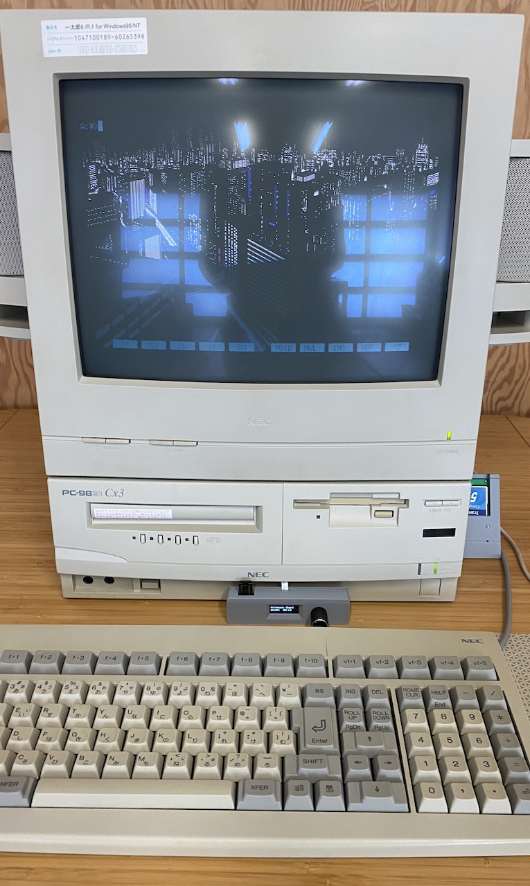
https://github.com/user-attachments/assets/1192d630-0beb-47c9-abd5-1f5b6c1d0ba6
There are two (small) PCBs: One goes inside the Gotek, and the other forms the remote, along with a 3d printed case.
You'll need:
Assembly:
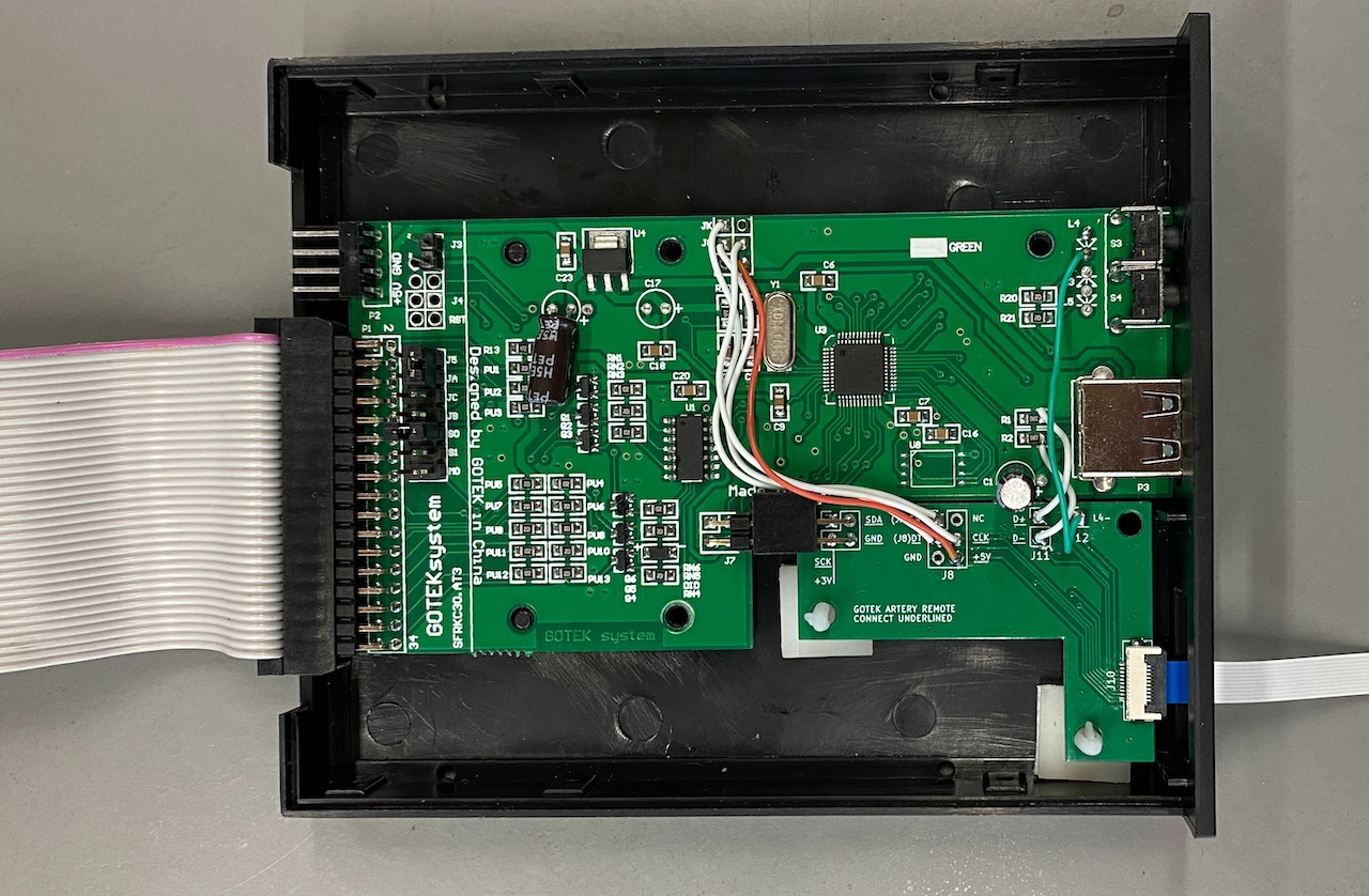
Connect the underlined connections. J8 mirrors the headers mid-board in these revisions of the Gotek, in the same positions, only the underlined connections are needed. J11 goes to the right side of R1 and R2 (in the same order). Make an effort to have these USB jumper wires the same length, and as short as possible. Optionally, J12 goes to the bottom side of the L4 activity LED (replacing the LED). The right-angle connector will make the board slip into place.
Connect the FFC, feed it through the hole left by the screen and out the front of your PC. Hook up the floppy side of things.
When assembling the remote, you'll probably have to desolder the angle pins of the rotary encoder and solder in straight ones. For both the rotary encoder and the OLED screen, the boards will be connected on the right side, so place a spacer on the left side to match height for better support - I use sticky tack. Trim the excess off the header pins for a flush fit.
Assemble the remote in this order:
I use these options in ff.cfg:
display-type = oled-128x32-rotate-slowrotary = half| Qty | Value | Footprint | References |
|---|---|---|---|
| 4 | MountingHole_2.2mm_M2 | MountingHole:MountingHole_2.2mm_M2 | H1, H2, H3, H4 |
| 3 | MountingHole_3.2mm_M3 | MountingHole:MountingHole_3.2mm_M3 | H5, H6, H7 |
| 2 | FFC 10x1 0.5mm | Connector_FFC-FPC:Molex_54548-1071_1x10-1MP_P0.5mm_Horizontal | J1, J10 |
| 1 | 10K | Resistor_THT:R_Axial_DIN0411_L9.9mm_D3.6mm_P12.70mm_Horizontal | R11 |
| 1 | 22u | Capacitor_THT:CP_Radial_D5.0mm_P2.50mm | C1 |
| 1 | Activity LED Cathode | Connector_PinHeader_2.54mm:PinHeader_1x01_P2.54mm_Vertical | J12 |
| 1 | Encoder | Connector_PinHeader_2.54mm:PinHeader_1x05_P2.54mm_Vertical | J4 |
| 1 | J7 Right Angle Connector | Connector_PinHeader_2.54mm:PinHeader_2x02_P2.54mm_Vertical | J7 |
| 1 | J8 Mirror | Connector_PinHeader_2.54mm:PinHeader_2x03_P2.54mm_Vertical | J8 |
| 1 | LED | LED_THT:LED_D3.0mm | D11 |
| 1 | OLED | Connector_PinHeader_2.54mm:PinHeader_1x04_P2.54mm_Vertical | J3 |
| 1 | USB Breakout | Connector_PinHeader_2.54mm:PinHeader_1x02_P2.54mm_Vertical | J11 |
| 1 | USB_A | Connector_USB:USB_A_Molex_67643_Horizontal | J2 |
It measures 101.5 × 93 mm and has 2 copper layers, 1.6 mm thick.
19 parts. The full list of its parts is on this page, with links to each part's symbol and footprint where PCBKit's library has them.
From the partlyhuman/gotek-remote repository on GitHub, at the commit this page was made from: the board is pcb/gotek-breakout.kicad_pcb and its schematic pcb/gotek-breakout.kicad_sch. PCBKit opens the board in the browser, with nothing to install.
Its repository publishes it under the MIT licence: you may reuse it on that licence's terms (keep the author's notice, and for a copyleft licence share your changes alike).

hackclub/OnBoard
💡 Join 1,000 teenagers and make your first PCB with a $100 grant!

polpo/picogus
Emulation of ISA sound cards and CD-ROM on Raspberry Pi Pico (GUS, SB/Adlib, MPU-401, Tandy, CMS, Panasonic CD-ROM) with USB mouse/joystick support


nkitanov/iaq_board
IAQ Board is a DIY (Do-It-Yourself) device for measuring internal air quality


Ardumower/ardumower
Develop an open source robotic lawn mower (HW+SW reference platform)

zmaker/arduino_cookbook
gli sketch del nuovo progetto Arduino Cookbook e dei video di YouTube