
2 layers21.1 × 26.9 mm

 pablomaki/metronome
A simple PCB originally designed to be a metronome. Output is frequency adjustable squarewave with 0.5 duty cycle that can be used for example to drive a simple speaker to produce stable rhythm.
Metronome is an open-source printed circuit board by pablomaki, from the pablomaki/metronome repository on GitHub. It is a 2-layer board of 34.5 × 48.8 mm with 26 parts on 30 nets, routed with 106 tracks and 0 vias.
It is built around the BS170. Its parts include 6 resistors, 6 diodes, 3 capacitors, 3 connectors and 2 ICs.
| ❗ NOTE |
|---|
| This design is still work in process. PCB has been confirmed to work on breadboard, but actual PCB is still in mail. After the PCB has been confirmed to be functioning properly, I will add BOM and design an enclosure for it. |
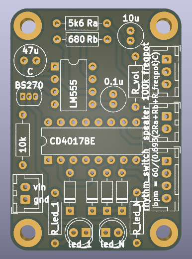
This metronome PCB is based on a simple 555 oscillator producing frequency adjustable square wave with 0.5 dutycycle. In addition the board contains CD4017BE counter circuit that can be used to drive two separate LEDs so that one flashes either every 2, 3 or 4 beats while the other flashes on every beat. The length of a bar can be chosen by separate switch or just hardwired for specific one.
The metronome works with supply voltage of 5 to 15 V, 9V battery is recommended and works well for this purpose. Note that the voltage used may affect the loudness of the speaker. Loudness can also be affected by a separate volume resistor.
TO BE ADDED
TO BE ADDED
| Qty | Value | Footprint | References |
|---|---|---|---|
| 4 | 1N4148 | Diode_THT:D_DO-35_SOD27_P7.62mm_Horizontal | D3, D4, D5, D6 |
| 4 | MountingHole_Pad | MountingHole:MountingHole_3.2mm_M3_ISO7380_Pad | H1, H2, H3, H4 |
| 2 | 2.2k | Resistor_THT:R_Axial_DIN0207_L6.3mm_D2.5mm_P10.16mm_Horizontal | R9, R10 |
| 2 | Conn_01x02 | Connector_JST:JST_XH_B2B-XH-A_1x02_P2.50mm_Vertical | J1, J2 |
| 1 | 0.1u | Capacitor_THT:C_Radial_D5.0mm_H11.0mm_P2.00mm | C3 |
| 1 | 100k | Connector_JST:JST_XH_B3B-XH-A_1x03_P2.50mm_Vertical | RV2 |
| 1 | 10k | Resistor_THT:R_Axial_DIN0207_L6.3mm_D2.5mm_P10.16mm_Horizontal | R4 |
| 1 | 10u | Capacitor_THT:C_Radial_D5.0mm_H11.0mm_P2.00mm | C2 |
| 1 | 4017 | Package_DIP:DIP-16_W7.62mm | U2 |
| 1 | 47u | Capacitor_THT:C_Radial_D6.3mm_H11.0mm_P2.50mm | C4 |
| 1 | 500 | Resistor_THT:R_Axial_DIN0207_L6.3mm_D2.5mm_P10.16mm_Horizontal | R3 |
| 1 | 5k | Resistor_THT:R_Axial_DIN0207_L6.3mm_D2.5mm_P10.16mm_Horizontal | R2 |
| 1 | BS170 | Package_TO_SOT_THT:TO-92_Inline | Q1 |
| 1 | Conn_01x04 | Connector_JST:JST_XH_B4B-XH-A_1x04_P2.50mm_Vertical | J3 |
| 1 | LED1 | LED_THT:LED_D5.0mm | D7 |
| 1 | LED234 | LED_THT:LED_D5.0mm | D2 |
| 1 | LM555xN | Package_DIP:DIP-8_W7.62mm | U1 |
| 1 | R_vol | Resistor_THT:R_Axial_DIN0207_L6.3mm_D2.5mm_P10.16mm_Horizontal | R1 |


pablozg/freeds
Derivador de energía solar excedente creado por Pablo Zerón, Diseño PCB por Amcalo, Tester original por Aeizoon, Wiki por Zoilo Mora

PhysicsDptAngers/polyUAnalog
Open source, analog and polyphonic synthesizer


DRWJSCHMIDT/T41
This is the repository for the officially released V10, V11, and V12 versions of the T41 Software Defined Transceiver hardware and kits.

sffubs/dactyl_manuform_gimbal
Instrutions and designs for building the dactyl-manuform-gimbal keyboard
It measures 34.5 × 48.8 mm and has 2 copper layers, 1.6 mm thick.
26 parts, built around the BS170. The full list of its parts is on this page, with links to each part's symbol and footprint where PCBKit's library has them.
From the pablomaki/metronome repository on GitHub, at the commit this page was made from: the board is kicad/metronome.kicad_pcb and its schematic kicad/metronome.kicad_sch. PCBKit opens the board in the browser, with nothing to install.
Its repository states no licence, so its author keeps all rights: ask pablomaki before reusing the design.