4 layers72 × 44 mm
Picflash board
nthclrd/picflash
Programmeur PIC open source en Rust : remplace MPLAB IPE/XC8 pour les PIC16, pilote les PICkit 4/5/Basic ou une carte RP2040 maison (KiCad)
115 parts1MIT

 p1lotz/Wardriver
Wardriver (the definition of a device scanning for wireless networks) but better! Featuring Wifi and Bluetooth scanning with a gps module, it's a great monitor as a small project (and as a Half-Life Hackclub project!!)
Wardriver is an open-source printed circuit board by p1lotz, from the p1lotz/Wardriver repository on GitHub, published under the MIT licence. It is a 2-layer board of 65 × 95 mm with 40 parts on 54 nets, routed with 503 tracks and 102 vias.
It is built around the ESP32-S3-WROOM-1U-N16R8, AP2112K-3.3 and AO3401A, with the SS34 among its other parts. Its parts include 11 resistors, 10 capacitors, 7 switches, 4 ICs and 4 diodes. It belongs with the radio and wireless boards and the ESP32 boards of this library.


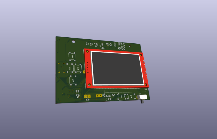
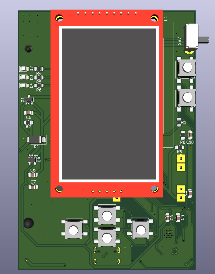
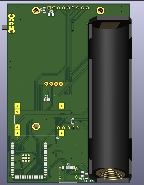
Hello yall! (My second README, have fun! <3) so this is a... wardriver! Well I like to call it a wi-fi/BLE scanner and monitor and I won't scan while from a moving vehicle but wardriver sounds cooler so yeah.
This is my second project which I actually did it all by myself (not unlike the software projects, let's not talk about those.)
This device scans wi-fi and bluetooth RFs and it also has GPS, and it uses the ESP32 Marauder (by justcallmekoko).
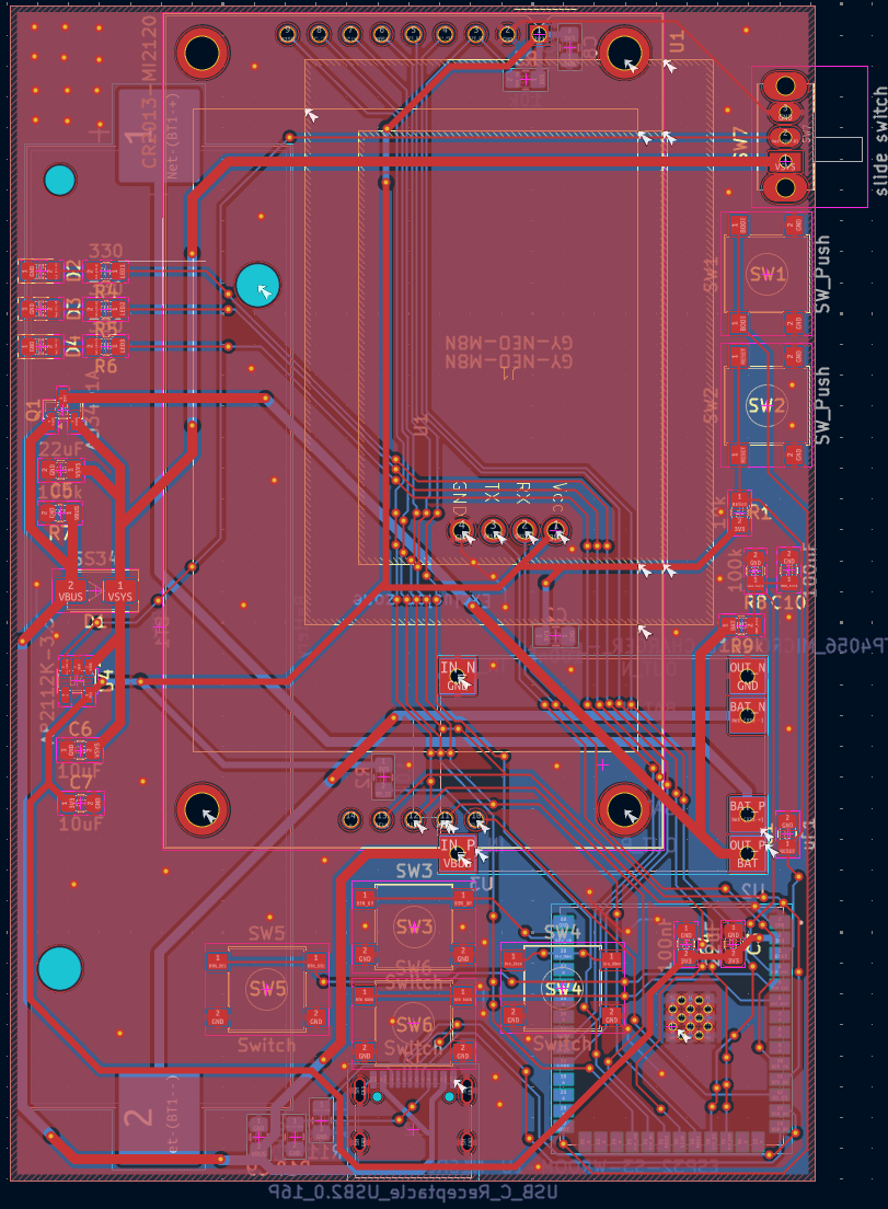
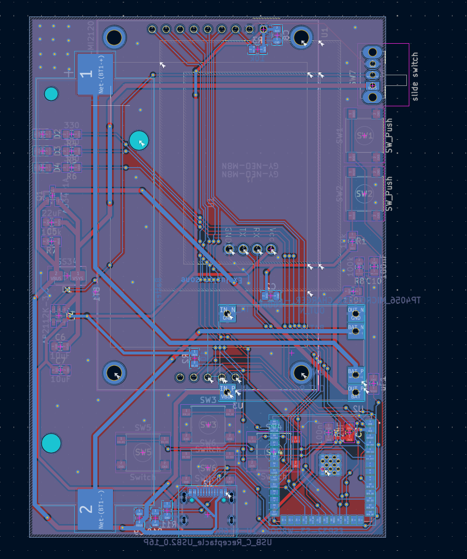
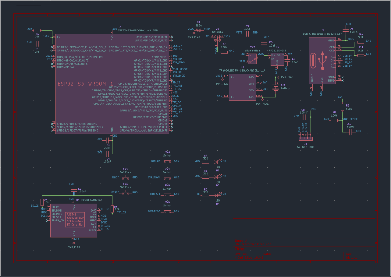
What else can I say, this project is a very interesting project and I am passionate on such things, on Radio Frequencies, scanning them, etc. and I have been wanting to make it for a long time. Its like when I think about it my heart starts racing with excitement!
Alright, I have made the enclosure too, took a bit, but its worth it, it looks LOVELYYY.
Images!
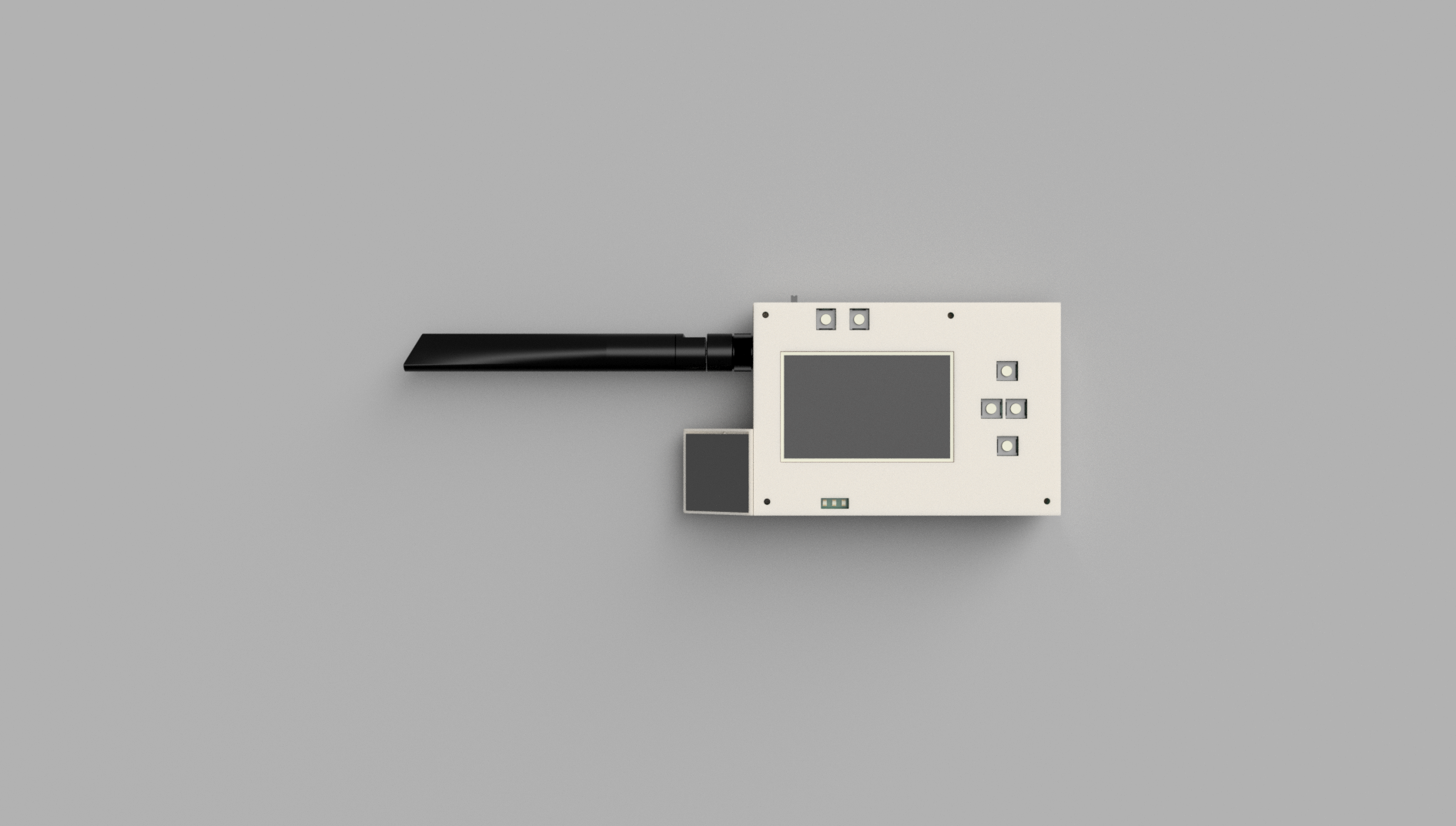
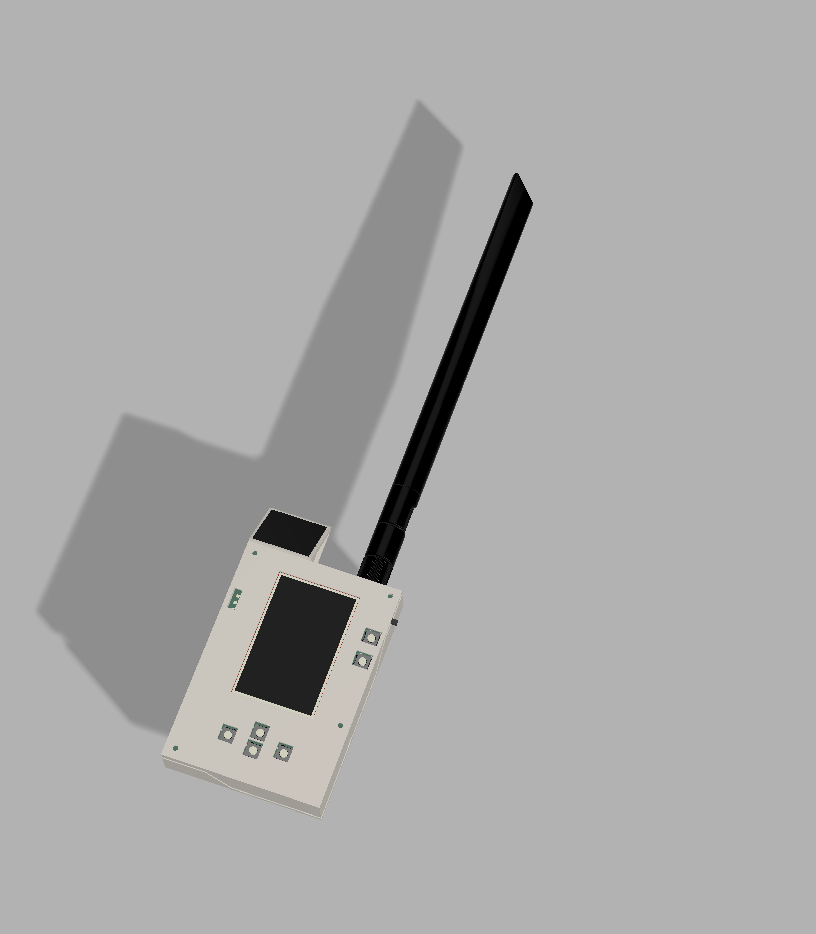
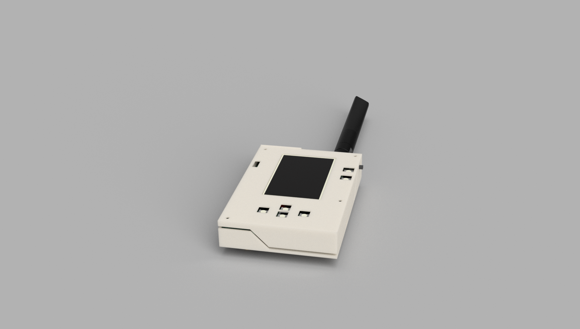
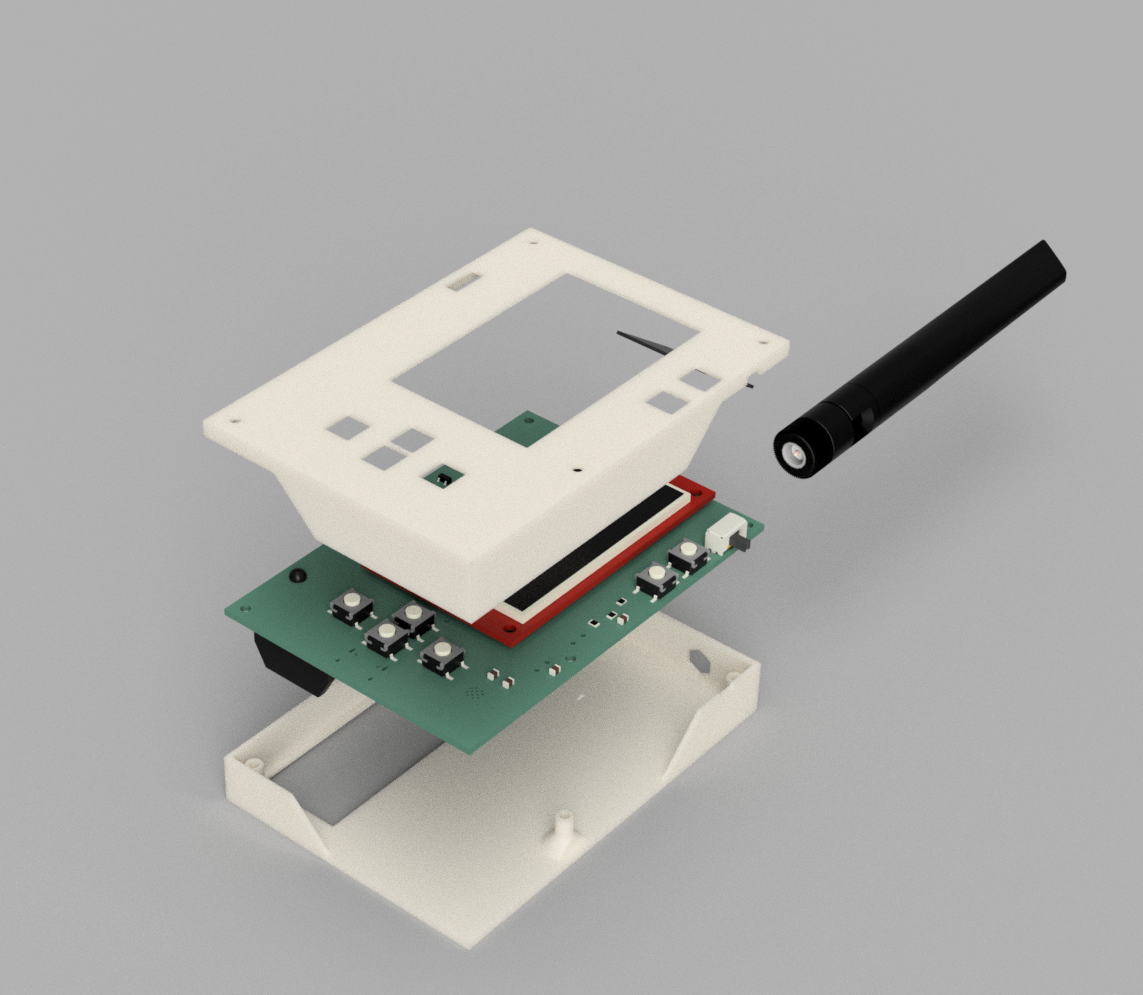

THE FIRMWARE. Yah the reviewer told me that I need it in here so here it is.
ESP32 Marauder by justcallmekoko Source: https://github.com/justcallmekoko/ESP32Marauder Pinned release: v1.20.0, 28 Oct 2026, https://github.com/justcallmekoko/ESP32Marauder/releases/tag/v1.20.0
| Module pad | GPIO | Net | Connects to |
|---|---|---|---|
| 3 | EN | RESET | SW2, reset button |
| 4 | GPIO4 | VBAT_SENSE | 100k/100k divider off BAT, ADC1_CH3 |
| 5 | GPIO5 | BTN_SEL | SW5, select |
| 6 | GPIO6 | BTN_BACK | SW6, back |
| 10 | GPIO17 | GPS_TX | NEO-M8N TX, so ESP receive |
| 11 | GPIO18 | GPS_RX | NEO-M8N RX, so ESP transmit |
| 12 | GPIO8 | SD_CS | microSD chip select on the display module |
| 13 | GPIO19 | USB_DN | USB-C D- |
| 14 | GPIO20 | USB_DP | USB-C D+ |
| 17 | GPIO9 | TFT_RST | ILI9341 reset |
| 18 | GPIO10 | TFT_CS | ILI9341 chip select |
| 19 | GPIO11 | MOSI | shared SPI, display and SD |
| 20 | GPIO12 | SCLK | shared SPI, display and SD |
| 21 | GPIO13 | MISO | shared SPI, display and SD |
| 22 | GPIO14 | TFT_DC | ILI9341 data/command |
| 23 | GPIO21 | TFT_LED | display backlight |
| 27 | GPIO0 | BOOT | SW1, boot button |
| 31 | GPIO38 | LED1 | status LED through 330R |
| 32 | GPIO39 | LED2 | status LED through 330R |
| 33 | GPIO40 | LED3 | status LED through 330R |
| 38 | GPIO2 | BTN_DOWN | SW4, down |
| 39 | GPIO1 | BTN_UP | SW3, up |
#define ILI9341_DRIVER
#define TFT_WIDTH  240
#define TFT_HEIGHT 320

#define TFT_MISO 13
#define TFT_MOSI 11
#define TFT_SCLK 12
#define TFT_CS   10
#define TFT_DC   14
#define TFT_RST   9
#define TFT_BL   21
#define TFT_BACKLIGHT_ON HIGH

#define SPI_FREQUENCY 40000000
Then a target block in esp32_marauder/configs.h.
#ifdef MARAUDER_WARDRIVER
  #define HAS_BT
  #define HAS_BUTTONS
  #define HAS_SCREEN
  #define HAS_GPS
  #define HAS_SD
  #define USE_SD
  #define HAS_BATTERY
  #define HAS_PSRAM
#endif

// buttons, all active low to GND with internal pullups

#ifdef MARAUDER_WARDRIVER
  #define U_BTN  1
  #define D_BTN  2
  #define C_BTN  5
  #define B_BTN  6
  #define L_BTN -1
  #define R_BTN -1
  #define HAS_U
  #define HAS_D
  #define HAS_C
  #define U_PULL true
  #define D_PULL true
(BOM v1, I will cut costs to land under 65$, OR I will work more and make it fully finished for tier 3 of funding who knows :3)
| Qty | Value | Footprint | References |
|---|---|---|---|
| 4 | 100nF | Capacitor_SMD:C_0805_2012Metric_Pad1.18x1.45mm_HandSolder | C2, C4, C8, C10 |
| 4 | Switch | Button_Switch_SMD:SW_SPST_B3S-1000 | SW3, SW4, SW5, SW6 |
| 3 | 100k | Resistor_SMD:R_0805_2012Metric_Pad1.20x1.40mm_HandSolder | R7, R8, R9 |
| 3 | 10k | Resistor_SMD:R_0805_2012Metric_Pad1.20x1.40mm_HandSolder | R1, R2, R3 |
| 3 | 330 | Resistor_SMD:R_0805_2012Metric_Pad1.20x1.40mm_HandSolder | R4, R5, R6 |
| 3 | LED | LED_SMD:LED_0805_2012Metric_Pad1.15x1.40mm_HandSolder | D2, D3, D4 |
| 2 | 10uF | Capacitor_SMD:C_0805_2012Metric_Pad1.18x1.45mm_HandSolder | C6, C7 |
| 2 | 22uF | Capacitor_SMD:C_0805_2012Metric_Pad1.18x1.45mm_HandSolder | C3, C5 |
| 2 | 5.1k | Resistor_SMD:R_0805_2012Metric_Pad1.20x1.40mm_HandSolder | R10, R11 |
| 2 | SW_Push | Button_Switch_SMD:SW_SPST_B3S-1000 | SW1, SW2 |
| 1 | 10uF1 | Capacitor_SMD:C_0805_2012Metric_Pad1.18x1.45mm_HandSolder | C9 |
| 1 | AO3401A | Package_TO_SOT_SMD:SOT-23 | Q1 |
| 1 | AP2112K-3.3 | Package_TO_SOT_SMD:SOT-23-5 | U4 |
| 1 | Battery | Battery:BatteryHolder_Keystone_1042_1x18650 | BT1 |
| 1 | CR2013-MI2120 | Display:CR2013-MI2120 | U1 |
| 1 | ESP32-S3-WROOM-1U-N16R8 | ESP32-S3-WROOM-1U-N16R8:XCVR_ESP32-S3-WROOM-1U-N16R8 | U2 |
| 1 | GY-NEO-M8N | GY-NEO-M8N:GY-NEO-M8N | J1 |
| 1 | SS34 | Diode_SMD:D_SMA | D1 |
| 1 | TP4056_MICRO-USB_CHARGER_-_1A | TP4056_MICRO-USB_CHARGER_-_1A:MODULE_TP4056_MICRO-USB_CHARGER_-_1A | U3 |
| 1 | USB_C_Receptacle_USB2.0_16P | Connector_USB:USB_C_Receptacle_HRO_TYPE-C-31-M-12 | J2 |
| 1 | slide switch | Button_Switch_THT:SW_Slide_SPDT_Angled_CK_OS102011MA1Q | SW7 |
| 1 | uF1 | Capacitor_SMD:C_0805_2012Metric_Pad1.18x1.45mm_HandSolder | C1 |
nthclrd/picflash
Programmeur PIC open source en Rust : remplace MPLAB IPE/XC8 pour les PIC16, pilote les PICkit 4/5/Basic ou une carte RP2040 maison (KiCad)


Alwwex/Cyklopo-ta-
Nosná deska 43 × 64 mm, na kterou se připájí Waveshare ESP32-C3-Zero, připojí displej, GPS a Li-Po baterie. Řeší všechno, co na nepájivém poli chybělo: nabíjení přes USB-C s „power-path“, vypínač, 3,3 V stabilizátor…


g210101021/OpenStylophone-RP2040
Overview • Technical Summary • Architecture • Hardware Audit & Remediation • Schematic Subsystems • PCB Layout • Firmware Roadmap • Bill of Materials • Author

jadenrhee/wigglecam-controller
RP2040 co-processor board for a 4-lens wigglegram camera: constant-current flash, controls, battery telemetry, Pi 5 I2C interface. 4-layer, DRC-clean, fab-ready.

jonny190/TableLight
A 3D-printable, battery-powered, USB-C rechargeable table lamp in the classic "Poldina" shape - honeycomb disc base, thin stem, down-firing cone shade with a white top - running WLED on an ESP32, with a capacitive touch…

It measures 65 × 95 mm and has 2 copper layers, 1.6 mm thick.
40 parts, built around the ESP32-S3-WROOM-1U-N16R8, AP2112K-3.3, AO3401A and SS34. The full list of its parts is on this page, with links to each part's symbol and footprint where PCBKit's library has them.
From the p1lotz/Wardriver repository on GitHub, at the commit this page was made from: the board is PCB/Wardriver.kicad_pcb and its schematic PCB/Wardriver.kicad_sch. PCBKit opens the board in the browser, with nothing to install.
Its repository publishes it under the MIT licence: you may reuse it on that licence's terms (keep the author's notice, and for a copyleft licence share your changes alike).