2 layers57.3 × 19 mm

 Owen-Ball/Electronic-Load
A 120W & 7.5A DIY electronic load
Filter board is an open-source printed circuit board by Owen-Ball, from the Owen-Ball/Electronic-Load repository on GitHub. It is a 2-layer board of 123 × 55 mm with 26 parts on 3 nets.
It is built around the EMHB630ARA471MMH0S and IHLP5050FDER1R0M01. Its parts include 19 capacitors, 4 connectors, 2 resistors and 1 inductor.


A DIY electronic load capable of
The design uses a custom PCB featuring an ESP32S3 Feather microcontroller. 4 power FETs dissipate the power via a CPU heatsink and current is measured using a bank of power resistors. With proper calibration, measurements/setpoints are within 1% across the entire operational range.
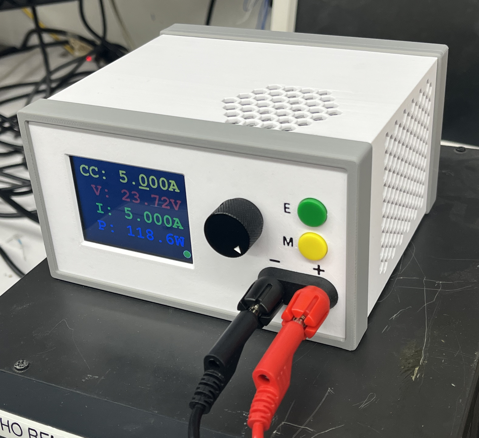
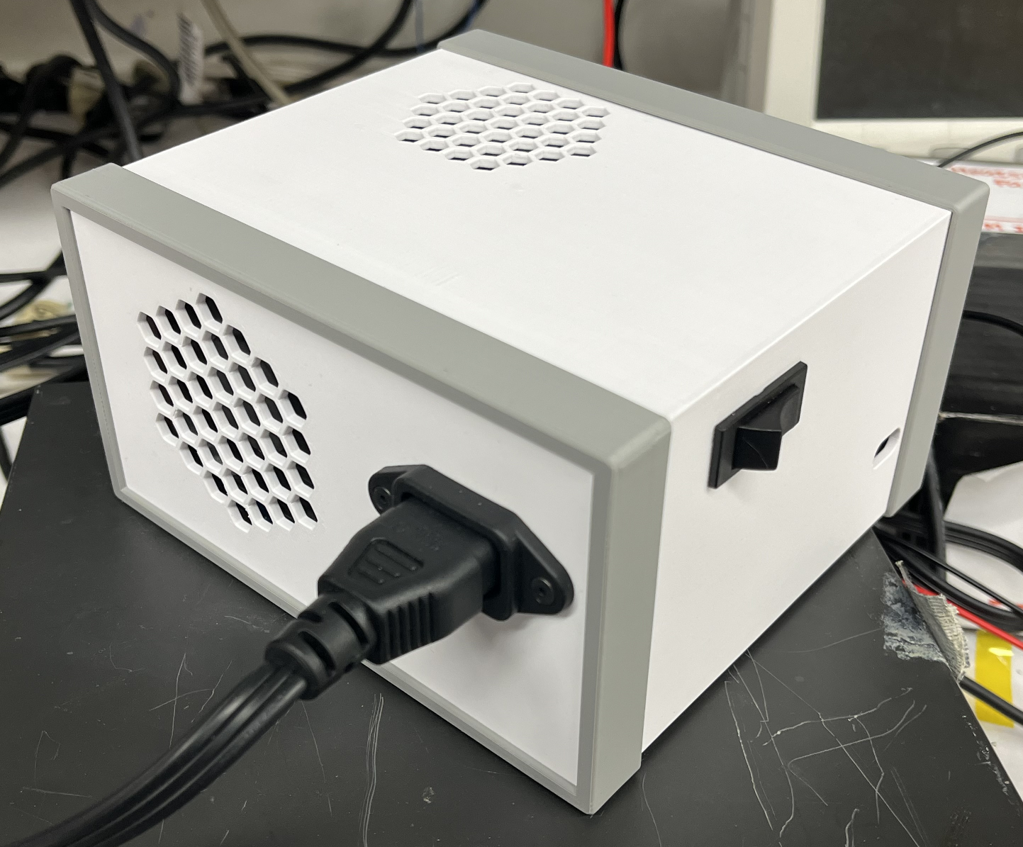
This section provides a brief overview of device operation, including
There are 5 "screens" on the UI, corresponding to the 4 operating modes of the device and a calibration screen. These are cycled through with the "mode" (M) button. The current mode is indicated in the top left. On each screen, the output can be enabled with the "enable" (E) button.
On each screen, the top-most value is the setpoint for the mode. This value is changed via the encoder. The 3 values below this are the measured values, which consist of the voltage, current, and either the power or discharged mAh in the case of battery mode. The temperature is also displayed at the bottom, along with any error messages. The output state is indicated by a red (off) or green (on) circle in the bottom right.
On each screen, the rotary encoder can be used to change the setpoint within the system bounds. The place value being edited can be changed by clicking the encoder to cycle through place values, or by pressing down the encoder and turning it.
Once on the desired mode and with the correct setpoint, the enable button can be used to toggle the system output. The output indicator will turn green. If the output turns off unexpectedly, an error/warning message should be displayed indicating the reason, with most of these going away next time the enable button is pressed.
All modes operate in general by very roughly setting a current, maybe with 10-25% accuracy. The actual current is monitored and used to adjust the setpoint. This is done with an integral controller, which requires some sanity checking to ensure system safety. If there is no source connected (or it is underpowered), the system will detect this and shut off the output. More specifically, if the set current and measured current are not within a certain tolerance of each other for a set amount of time, the output is disabled.
Other reasons for system shutoff are voltage or temperature limits being exceeded. In CR or CP modes, since the current is automatically calculated the output will be shut off if the system tries to set the current or power above the system limit.
In rare circumstances the system can oscillate. This will occur in the presence of a slow responding source in series (ie an incandescent bulb) or through interactions with the feedback system of a power supply. There is no protection against this, so turn the system off if observed.
While the system has some reverse polarity protection, it is highly recommended that this is not relied on. As such, make sure to connect the higher potential of the source to the +/red terminal and the lower to the -/black terminal. While the system should draw no current while powered off, I recommend having the system powered before connecting a source.
When connecting to the Feather using a USB-C cable, a cable with the 5V line cut is recommended. The system has diodes on the 5V lines so there are no shorting risks, but for some reason the system measurements differ by around 1% depending on whether the system receives USB power or not. Thus for calibration using the serial monitor, a cable with no power is essential.
The system can be put into bootloader mode by pressing down the encoder while turning on the system (assuming you bridge the encoder pin and bootloader testpad on the feather together).
Additionally, please use caution when operating the device, as mains 120V power is used. There are potential areas of risk, including power supply failure and improper crimping for the live wires.
The microcontroller used is the ESP32S3 feather. This was done with the intention of adding WiFi support to the device for the monitoring and setting of parameters. However, the ESP32S3 has issues using both the ADC and WiFi at the same time, so this feature is on hold. Additionally, I did not have any significant use cases for the WiFi anyways. If not implementing WiFi functionality, the ESP32 is a poor choice due to the extremely non-linear ADCs that mandate extensive calibration.
The bulk of the power is burned using 4 IRFB7545PBF NCH MOSFETs (TO-220). The FETs are mounted to a CPU heatsink to thermally couple them and provide power dissipation. Current measurements are done using the voltage across banks of RSMF2JT4R70 4.7 Ohm resistors. Each FET is in series with a bank of 4 of these resistors in parallel. The resistors are cooled via a fan mounted to the system case.
A 10A fuse is placed in series with the + input to the system. Some degree of reverse polarity protection is present in the form of a reverse biased diode across the input ports after the fuse. This ideally will limit reverse voltages to less than 1V but has not been tested.
All sensing is done via the ADCs on the ESP32S3. Accurary could be improved by purchasing more accurate standalone ICs for voltage and current measurements however.
Voltage sensing has two ranges, 0-12V and 0- 40V (need to check). Thus for a 12-bit ADC, resolution is around 3mV/step and 10mV/step. Both sensors operate using a simple voltage divider to divide down the max voltage to the maximum ADC input of ~3.2V. 7.5V zener diodes are used to clamp the voltage input to the ADCs to ~3.75V. 7.5V zeners are used since lower voltage zeners feature a less sharp turn on that would increase leakage and worsen the voltage clamping. One note is the pin used for the high voltage range on the ESP32S3 feather has an SMD LED attached to it (not sure why they put the on-board LED on an analog in pin...). For high voltage inputs, this drives the LED, which is not ideal and causes non-linearity in the measurement that needs to be compensated for. The LED could of course be removed, but I did not do this.
Current sensing is done with two ranges as well, although there are some major design oversights. The original intention was to have two operating modes, one where all 4 FETs were running and one were only a single one was active. This would enable higher precision for low current measurements. Thus 3 of the 4 FETs are controlled by 1 DAC and the final one is controlled by a separate DAC.
The high sensitivity current sensor amplies the voltage across the power resistors by a factor of 10. Thus for 16 shunt resistors, this range maxes out around 1.1A. The design oversight is that this sensor is only hooked up to the independently controlled FET path, so in high current mode, this sensor is not truly measuring the current, it is "guessing" based on a measurement of 1/4 of the current.
The low sensitivity (higher range) current sensor uses resistors to average the voltages across the 4 shunts. This means it works properly in high current mode, but not in low, since this setup will not work when only the one FET is active. This mode peaks at around 10A (need to check).
As a summary of the design oversights, the only fully functioning current sensing modes would be high current mode + low sensitivity sensor and low current mode, high sensitivity sensor. After discovering this issue, I cut support for low current mode (single power FET active) entirely since I currently do not have a use case for the mode (would be 0-250mA), although this may be added in the future. I did decide to use the high sensitivity current sensor in high current mode despite only directly measuring 1/4 of the current. For current runaway reasons, the system will still take a reading using the low sensitivity current sensor to ensure current does not run away in a FET not monitored by the high sensitivity current sensor.
More details regarding the firmware implementation can be found in the firmware-specific readme here
This includes:
| Qty | Value | Footprint | References |
|---|---|---|---|
| 7 | EMHB630ARA471MMH0S | FilterBoardLib:EMHB630ARA471MMH0S | C1, C2, C3, C4, C5, C6, C7 |
| 6 | .1u | Capacitor_SMD:C_0805_2012Metric | C11, C12, C13, C17, C18, C19 |
| 6 | 1u | Capacitor_SMD:C_0805_2012Metric | C8, C9, C10, C14, C15, C16 |
| 2 | 47k | Resistor_SMD:R_0805_2012Metric | R1, R2 |
| 2 | Conn_01x01_Pin | FilterBoardLib:Wire_Pad | J3, J4 |
| 1 | Banana Terminals | FilterBoardLib:Banana_Terminals | J2 |
| 1 | IHLP5050FDER1R0M01 | FilterBoardLib:IND_IHLP-5050FD-01_VIS | L1 |
| 1 | ~ | FilterBoardLib:Banana_Terminals | J1 |
It measures 123 × 55 mm and has 2 copper layers, 1.6 mm thick.
26 parts, built around the EMHB630ARA471MMH0S and IHLP5050FDER1R0M01. The full list of its parts is on this page, with links to each part's symbol and footprint where PCBKit's library has them.
From the Owen-Ball/Electronic-Load repository on GitHub, at the commit this page was made from: the board is FilterBoard/PCB/filter_board.kicad_pcb and its schematic FilterBoard/PCB/filter_board.kicad_sch. PCBKit opens the board in the browser, with nothing to install.
Its repository states no licence, so its author keeps all rights: ask Owen-Ball before reusing the design.

hackclub/OnBoard
💡 Join 1,000 teenagers and make your first PCB with a $100 grant!


harbaum/galagino
A Galaga, Pac-Man and Donkey Kong arcade emulator for the ESP32

Luos-io/luos_engine
Open-source and real-time orchestrator for cyber-physical-systems, to easily design, test and deploy embedded applications and digital twins.

google/walt
A device for measuring latency of physical sensors and outputs on phones and computers
