
4 layers129 × 104.6 mm

 owalkhoff/Free_Sunshine
Promoting mechatronic art & sustainable energy in South Africa one g☼ggab☼t at a time
Goggabot is an open-source printed circuit board by owalkhoff, from the owalkhoff/Free_Sunshine repository on GitHub. It is a 2-layer board of 55 × 33 mm with 21 parts on 7 nets, routed with 21 tracks and 4 vias.
It is built around the BC817 and BC807. Its parts include 8 connectors, 4 resistors and 3 transistors. It belongs with the power boards of this library.
Promoting mechatronic art & sustainable energy in South Africa one g☼ggab☼t at a time
It is about spreading access to and an interest in electronics and art.
It also raises awareness about sustainable energy and the current development in South Africa of legislation regarding small scale solar energy generators. The project is driven by Miranda Moss and Oliver Walkhoff and is made possible with the support of the Swiss Arts Council Pro Helvetia. Find out more on the project website:
A g☼ggab☼t is a small solar-powered robot. About 200 of them have been built in workshops during ISEA 2018, Durban, and subsequently at Baleni Senior Secondary School, Kwazulu Natal, South Africa.
A g☼ggab☼t consists of a printed circuit board (pcb), one or two solar cells, a motor, a capacitor and some mechanical parts. For the workshops, the pcb was pre-populated with smd components. The participants soldered the larger components to the board and added bristles, wire, beads and other things to create their individual bot.
We have created a pamphlet with a short description of the parts and some building instructions:
A schematic and a short description of the g☼ggab☼t circuit is also on the pamphlet. It was contributed by Uwe Schüler of Kulturgüter-Schuppen, Dusslingen, Germany.
The pcb was created using KiCad Version 4.0.7. The boards were manufactured by PCBWay in China, and assembled by R2 Manufacturing, Glattbrugg, Switzerland.
The KiCad and Gerber files which were used for production can be found in this repository.
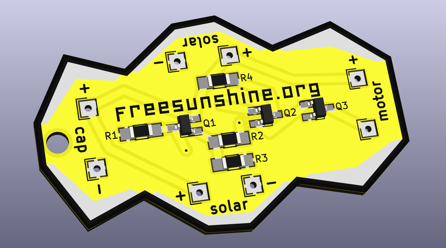
This is a rendering of the front, with components:
And here is the back:
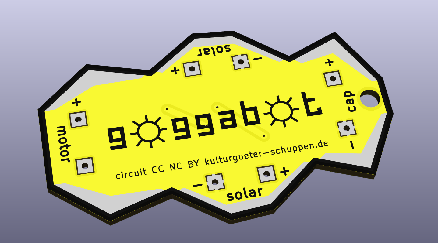
The g☼ggab☼t circuit is CC NC BY kulturgueter-schuppen.de.
| Qty | Value | Footprint | References |
|---|---|---|---|
| 4 | Mot1 | Socket_Strips:Socket_Strip_Straight_1x01 | J1, J2, J3, J4 |
| 3 | Pwr2 | Socket_Strips:Socket_Strip_Straight_1x01 | J5, J6, J7 |
| 2 | 1M | Resistors_SMD:R_1206_HandSoldering | R1, R3 |
| 2 | BC817 | TO_SOT_Packages_SMD:SOT-23_Handsoldering | Q2, Q3 |
| 2 | LOGO | Gogga:goggabot_55x33_outline_1mm | outline, outline |
| 2 | LOGO | Gogga:goggabot_55x33_mask | mask, mask |
| 1 | 180k | Resistors_SMD:R_1206_HandSoldering | R2 |
| 1 | 1k | Resistors_SMD:R_1206_HandSoldering | R4 |
| 1 | BC807 | TO_SOT_Packages_SMD:SOT-23_Handsoldering | Q1 |
| 1 | LOGO | Gogga:goggabot_logo_34x6 | goggabot |
| 1 | LOGO | Gogga:goggabot_freesunshine_31x3 | freesunshine |
| 1 | Mot2 | Socket_Strips:Socket_Strip_Straight_1x01 | J8 |
It measures 55 × 33 mm and has 2 copper layers, 1.6 mm thick.
21 parts, built around the BC817 and BC807. The full list of its parts is on this page, with links to each part's symbol and footprint where PCBKit's library has them.
From the owalkhoff/Free_Sunshine repository on GitHub, at the commit this page was made from: the board is goggabot/kicad-4/goggabot.kicad_pcb. PCBKit opens the board in the browser, with nothing to install.
Its repository states no licence, so its author keeps all rights: ask owalkhoff before reusing the design.

MR-DOS/TDR_diploma_thesis
Time domain reflectometer. Includes Hardware, firmware and GUI in Octave. Also a diploma thesis.


PySpice-org/eda-rw
Python library to read/write KiCad and LibrePCB Sexpr file format


