2 layers160 × 100 mm
 hggh/kitchen-timer16
kitchen timer
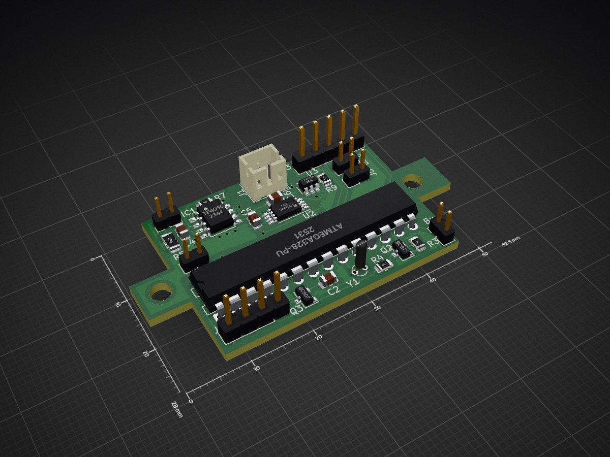
Kitchen timer is an open-source printed circuit board by hggh, from the hggh/kitchen-timer repository on GitHub, published under the GPL-3.0 licence. It is a 2-layer board of 52.5 × 28 mm with 35 parts on 41 nets, routed with 268 tracks and 18 vias.
It is built around the ATMEGA328-PU, DW01A and FS8205A, with the TP4056, BC817 and BC807 among its other parts. Its parts include 10 resistors, 7 connectors, 5 capacitors, 4 ICs and 3 transistors. It belongs with the AVR (ATmega, ATtiny) boards of this library.


| Qty | typ |
|---|---|
| 3 | 100nf smd 0805 |
| 2 | 10µF smd 0805 |
| 1 | TP4056 |
| 2 | BC817 |
| 1 | BC807 |
| 2 | 10k smd 0805 |
| 3 | 2.6k smd 0805 |
| 1 | 0.4 smd 1206 |
| 1 | 20k smd 0805 |
| 1 | 2k smd 0805 |
| 1 | 100 smd 0805 |
| 1 | 1k smd 0805 |
| 2 | 4.7k smd 0805 |
| 1 | ATmega 328-PU |
| 1 | FS8025A |
| 1 | DW01A |
| 1 | 32khz crystal |
| 1 | KY-040 |
| 1 | battery holder 18650 |
| 1 | lipo 18650 |


| Qty | Value | Footprint | References |
|---|---|---|---|
| 3 | 2.6k | Resistor_SMD:R_0805_2012Metric | R2, R3, R4 |
| 2 | 100nf | Capacitor_SMD:C_0805_2012Metric | C2, C3 |
| 2 | 10µF | Capacitor_SMD:C_0805_2012Metric | C4, C5 |
| 2 | 4,7k | Resistor_SMD:R_0805_2012Metric | R10, R11 |
| 2 | BC817 | Package_TO_SOT_SMD:SOT-23 | Q1, Q2 |
| 2 | MountingHole | MountingHole:MountingHole_3.2mm_M3 | H1, H2 |
| 2 | R | Resistor_SMD:R_0805_2012Metric | 10k1, 20k1 |
| 1 | 0.4 | Resistor_SMD:R_1206_3216Metric | R5 |
| 1 | 1.5k | Resistor_SMD:R_0805_2012Metric | R7 |
| 1 | 100 | Resistor_SMD:R_0805_2012Metric | R8 |
| 1 | 100nF | Capacitor_SMD:C_0805_2012Metric | C6 |
| 1 | 10k | Resistor_SMD:R_0805_2012Metric | R1 |
| 1 | 1k | Resistor_SMD:R_0805_2012Metric | R9 |
| 1 | 32khz | Crystal:Crystal_DS15_D1.5mm_L5.0mm_Vertical | Y1 |
| 1 | ATmega328-PU | Package_DIP:DIP-28_W7.62mm | U1 |
| 1 | BATT | Connector_JST:JST_PH_B2B-PH-K_1x02_P2.00mm_Vertical | J1 |
| 1 | BC807 | Package_TO_SOT_SMD:SOT-23 | Q3 |
| 1 | Buzzer | Connector_PinHeader_2.00mm:PinHeader_1x02_P2.00mm_Vertical | BZ1 |
| 1 | Conn_01x02_Male | Connector_PinHeader_2.00mm:PinHeader_1x02_P2.00mm_Vertical | J7 |
| 1 | DW01A | Package_TO_SOT_SMD:SOT-23-6 | U3 |
| 1 | FS8205A | Package_SO:TSSOP-8_4.4x3mm_P0.65mm | U2 |
| 1 | LCD | Connector_PinHeader_2.54mm:PinHeader_1x04_P2.54mm_Vertical | J4 |
| 1 | RT | Connector_PinHeader_2.54mm:PinHeader_1x05_P2.54mm_Vertical | J3 |
| 1 | RTC | Connector_PinHeader_2.00mm:PinHeader_1x02_P2.00mm_Vertical | J5 |
| 1 | SW2 | Connector_PinHeader_2.00mm:PinHeader_1x02_P2.00mm_Vertical | J2 |
| 1 | TP4056 | tp4056:TP4056_SOP-8-PP | IC1 |
| 1 | USB IN | Connector_PinHeader_2.00mm:PinHeader_1x02_P2.00mm_Vertical | J6 |
It measures 52.5 × 28 mm and has 2 copper layers, 1.6 mm thick.
35 parts, built around the ATMEGA328-PU, DW01A, FS8205A and TP4056. The full list of its parts is on this page, with links to each part's symbol and footprint where PCBKit's library has them.
From the hggh/kitchen-timer repository on GitHub, at the commit this page was made from: the board is pcb2/kitchen-timer.kicad_pcb and its schematic pcb2/kitchen-timer.kicad_sch. PCBKit opens the board in the browser, with nothing to install.
Its repository publishes it under the GPL-3.0 licence: you may reuse it on that licence's terms (keep the author's notice, and for a copyleft licence share your changes alike).


I-AM-ENGINEER/AudMX
Alternative for Deej ( https://github.com/omriharel/deej ) with more features

potpurri/LiPo_Charger_TP4056_BuckBoost_TPS63020
This PCB is designed to safely charge a lithium-ion cell and provide a selectable 3.3V or 5V output. It's equipped with components that ensure safe charging and protection for the battery and supports flexible output…

GuzziFlipFlops/ESP32-Walkie-Talkie
An open source ESPNOW based walkie talkie with a 600 meter tested distance, with an OLED and multiple buttons to interact with


telagod/moskill
MosKill - Smart Mosquito Swatter with BLE, Kill Counting & Statistics | ESP32-C3 + KiCad PCB + UniApp
