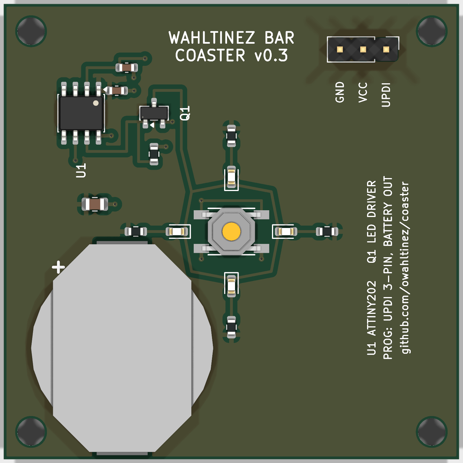
Coaster is an open-source printed circuit board by owahltinez, from the owahltinez/coaster repository on GitHub. It is a 2-layer board of 50 × 50 mm with 21 parts on 10 nets, routed with 50 tracks and 13 vias.
It is built around the ATTINY202-SSN, KT-0603W and AO3400A, with the CR20160J and TS-1187A-B-A-B among its other parts. Its parts include 5 resistors, 4 inductors, 3 capacitors, 1 IC and 1 transistor. It belongs with the AVR (ATmega, ATtiny) boards of this library.
Very simple battery-operated device. When you push a button, the light turns on for a few seconds
and then it turns off. It is designed to be used as a coaster such that, when gently pushing a glass
down on the device, the light activates making the contents of the glass glow.
Pressing down on the coaster triggers a ~8 second light show: the LEDs ramp up to full
brightness, "breathe" gently five times, and fade back to black. Between shows the device
sleeps at ~1 µA — there is no on/off switch and none is needed.
Repository layout
firmware/ — AVR C firmware and its build/flash Makefile.
pcb/ — v0.3 board design (KiCad, generated from python scripts) and footprints.
tools/ — pinned toolchain containers (KiCad for the board, avr-gcc for the firmware).
All subdirectories share the same verbs, and the top-level Makefile forwards to each:
make build (firmware hex + board + enclosure exports), make test (flash-fit check +
board DRC + enclosure solidity check), make clean. Domain-specific verbs forward to the
relevant subdirectory: make flash / make fuses (firmware programming),
make review (board render / PDF / STEP), make fab (JLCPCB order bundle). The
firmware and PCB verbs run inside pinned containers — make image builds them once
(see Software); flashing stays on the host.
How it works
The button connects an MCU pin (with its internal pull-up) to ground. Pressing it fires a
falling-edge interrupt on one of the ATtiny202's fully-asynchronous pins, which wakes the
chip from power-down sleep with the main clock stopped — a press costs effectively no
charge. The firmware debounces the edge, plays the show over hardware PWM through a
MOSFET driving four series-resistored LEDs, and goes back to sleep.
Two details carry hard-won lessons from v0.2:
The show also plays once when the battery is inserted (a power-on reset doubles as a
built-in self test), but only on a power-on reset: a brown-out reset means a dying
cell sagged below 1.8V mid-show, and playing again would loop the cell to death — so a
brown-out goes straight back to sleep and the coaster simply dims gracefully as the
battery wears out.
Wake edges that turn out not to be presses (e.g. contact bounce while lifting a glass
off a held-down button) are filtered by a 20ms debounce check, so the show plays on
deliberate presses only.
Hardware
The v0.3 design (KiCad) lives in pcb/:
pcb/design.py is the circuit as data — parts, placements, and the netlist defined
once. This is the file to read or edit; it is the source of truth.
pcb/DESIGN.md is the design specification: pin map, BOM with part rationale,
ordering plan, and the validation checklists.
pcb/generate.py turns design.py into coaster.kicad_pcb (committed for
convenience). make build regenerates the board and validates connectivity; make test runs DRC; make review produces a board render, a 1:1 printable PDF, and a STEP
model for CAD fit checks.
pcb/coaster.pretty/ — project footprints with pad geometry extracted from the
manufactured v0.2 board (battery holder, tactile switch).
There is no schematic: JLCPCB takes Gerbers + BOM + CPL (not a schematic), the board is
built and checked directly against design.py, and design.py itself documents the
circuit — so a derived schematic would add nothing.
The previous revision (v0.2: ATtiny13A, EasyEDA, CR2032) is archived at release
v0.2.1, including its
firmware, schematic renderings, and 3D printing assets.
Production
All SMD parts are LCSC-stocked, so the board can be fabricated and assembled through
JLCPCB — the only hand-assembly per unit is dropping a CR2016 into the holder. make fab writes the three JLCPCB uploads (Gerbers zip + BOM + CPL) to pcb/dist/; order
with white soldermask (the board face is the reflector behind the LEDs). The full
step-by-step — orientation checks, stock confirmation, post-assembly flashing — is the
ordering plan in pcb/DESIGN.md.
Rough per-unit estimates as of June 2026 (USD, assembled and shipped; ~A$1.55/US$):
Per unit
Qty 30
Qty 100
Qty 1k
Qty 10k
Parts
$0.74
$0.70
~$0.60
~$0.47
Feeder/setup/stencil
$0.72
$0.30
~$0.04
~$0
PCB + assembly
$0.47
$0.40
~$0.30
~$0.20
Board shipping
$0.20
$0.35
~$0.10
~$0.05
CR2016 (name-brand)
$0.65
$0.35
~$0.20
~$0.12
Enclosure
$0.60 (FDM)
$0.60 (FDM)
~$1.00 (print farm)*
~$0.30 (molded)*
Finished coaster
~$3.40
~$2.70
~$2.25
~$1.10
*The 1k column keeps FDM but prices it honestly: ~2,500 printer-hours, which a small
farm of four budget printers clears in under a month — filament plus printer
amortization lands near $1/unit, with no tooling commitment and the printers kept at
the end. The 10k column switches to injection molding (aluminum tooling, amortized);
that is also the column where a further redesign pays — shrinking the PCB from the
structural 50×50mm to a ~25mm puck and letting the molded shell carry the mechanical
roles would cut the PCB line by $0.10 more. If 1k is a milestone toward 10k rather
than the destination, rapid aluminum tooling ($1–1.5k) prices similarly at 1k and
carries forward.
The electronics architecture is the same in every column — the MCU ($0.30–0.43) is the
cheapest line that matters, and it is the entire personality of the product. Prices
drift; get a real quote from the JLCPCB quote tool and
confirm ATtiny202 stock at order time (the ATtiny402 is a firmware-compatible drop-in
substitute).
Software
The firmware and board builds run in pinned containers (tools/), so the host
needs neither a KiCad nor an AVR toolchain — only a container engine. Pinning is what
keeps the artifacts reproducible: the committed board is KiCad-10 format and host KiCad
drifts (Debian ships v9, which can't even open a v10 board), and the ATtiny202 firmware
needs avr-gcc ≥ 12 (the README used to hand-source avr-gcc@14 from the
osx-cross/avr tap on macOS). Build the
images once, then the verbs route through them automatically:
bash
make image               # build both images: coaster-fw + coaster-pcb (re-run after editing a Containerfile)
make build               # firmware hex + board + enclosure, each in its toolchain
make fab                 # regenerate the board + emit the JLCPCB bundle, in the container
The enclosure builds the same way, in a pinned FreeCAD 1.1.1 container (make image
builds it too) — so the host needs no FreeCAD either, and the old macOS freecadcmd
symlink dance is gone.
docker here is a Podman alias (podman-docker); override
CONTAINER_ENGINE to use another runtime. Rootless Podman maps container-root to your
UID (the Makefile passes --user 0), so generated files come back owned by you. The
rule is produce artifacts in a container, touch hardware on the host — so flashing
(make flash / make fuses, which need a USB-serial adapter) stays on the host and
needs avrdude (≥ 7, for serialupdi) installed there; see Flashing below.
The enclosure build still runs on the host via FreeCAD (freecadcmd); on macOS the
app bundle doesn't expose its CLI, so symlink it once:
No dedicated programmer needed: UPDI works over any USB-serial adapter with a single
~1kΩ resistor bridging the adapter's TX to RX, and RX wired to the board's UPDI pad
(plus VDD and GND — the J1 pads are labeled on the silkscreen).
bash
make flash   # writes main.hex over serialupdi
make fuses   # once per chip: brown-out detector at 1.8V, sampled in sleep
The fuses matter: the factory default leaves the BOD disabled, which allows undefined
behavior when the battery sags, and the firmware's brown-out logic depends on it.
For flashing a stack of boards hands-free, make flash-loop runs a continuous loop:
plug a board onto the jig, it flashes + fuses + verifies automatically, then waits for
you to remove it before arming the next. The board reports its own result — a good
flash plays a distinct rapid blink and a failed one stays dark, so you never look at the
screen. The blink is gated on a one-shot EEPROM flag the loop writes only after both
flash and fuses verify (a single avrdude run, which aborts before the arm step on any
earlier failure); the firmware blinks once on the next boot and clears the flag, so it
fires exactly once per flash and never again in the field.
Gotchas:
Remove the coin cell before flashing. The adapter drives VDD and would back-feed
the (non-rechargeable) lithium cell.
That's it. The v0.2 list of ISP gotchas (LEDs clamping MOSI, flaky readback, wedged
programmers) died with the ISP header: UPDI shares no pins with anything else on this
board, by construction.
Power estimates
Assumptions: CR2016 rated at 75 mAh (~70 mAh usable), ~8 mA LED draw at 100% duty on a
fresh cell, ~1 µA sleep current (BOD sampled).
Event
Cost
Notes
Light show (~8 s)
~15 µAh
avg ~60% LED duty + ~1.5 mA MCU active
Button press
~0
pin-change wake; nothing touches the supply
Standby (per day)
~26 µAh
~1 µA sleep + battery self-discharge
Expected battery life:
Usage pattern
Battery life
Never pressed (shelf)
~7 years
~5 presses/day
~2 years
~30 presses/day (bar duty)
~5 months
Theoretical max shows
~4,500
The punchline: v0.3 runs on a cell with a third of the v0.2 battery's capacity and
still matches its life, because presses are now free (each v0.2 press dead-shorted the
battery and cost as much as a show) and sleep current dropped ~4×.
It measures 50 × 50 mm and has 2 copper layers, 1.6 mm thick.
What parts does the Coaster use?
21 parts, built around the ATTINY202-SSN, KT-0603W, AO3400A and CR20160J. The full list of its parts is on this page, with links to each part's symbol and footprint where PCBKit's library has them.
Where can I download the Coaster KiCad files?
From the owahltinez/coaster repository on GitHub, at the commit this page was made from: the board is pcb/coaster.kicad_pcb. PCBKit opens the board in the browser, with nothing to install.
Can I use the Coaster design in my own project?
Its repository states no licence, so its author keeps all rights: ask owahltinez before reusing the design.
This repository contains all the necessary files and instructions for the PCBs that are designed using KiCad. Here is an overview of the main components: - .github: Contains Github-specific configurations, including…