

2 layers40 × 55.5 mm
 Outdatedcandy92/Radio-Tutorial
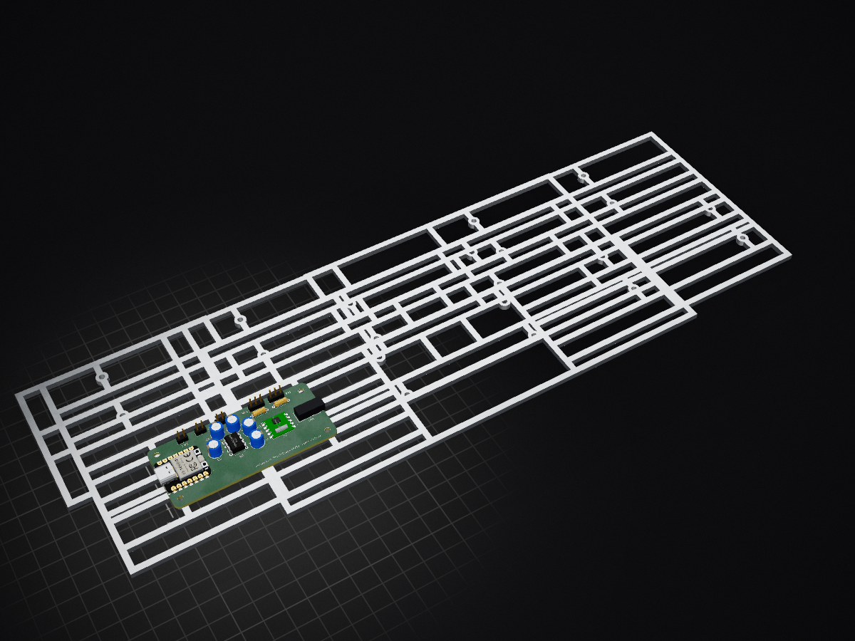
An FM receiver board built around the RDA5807 module. It includes a Seeed Xiao RP2040 to control the RDA5807 over I2C.
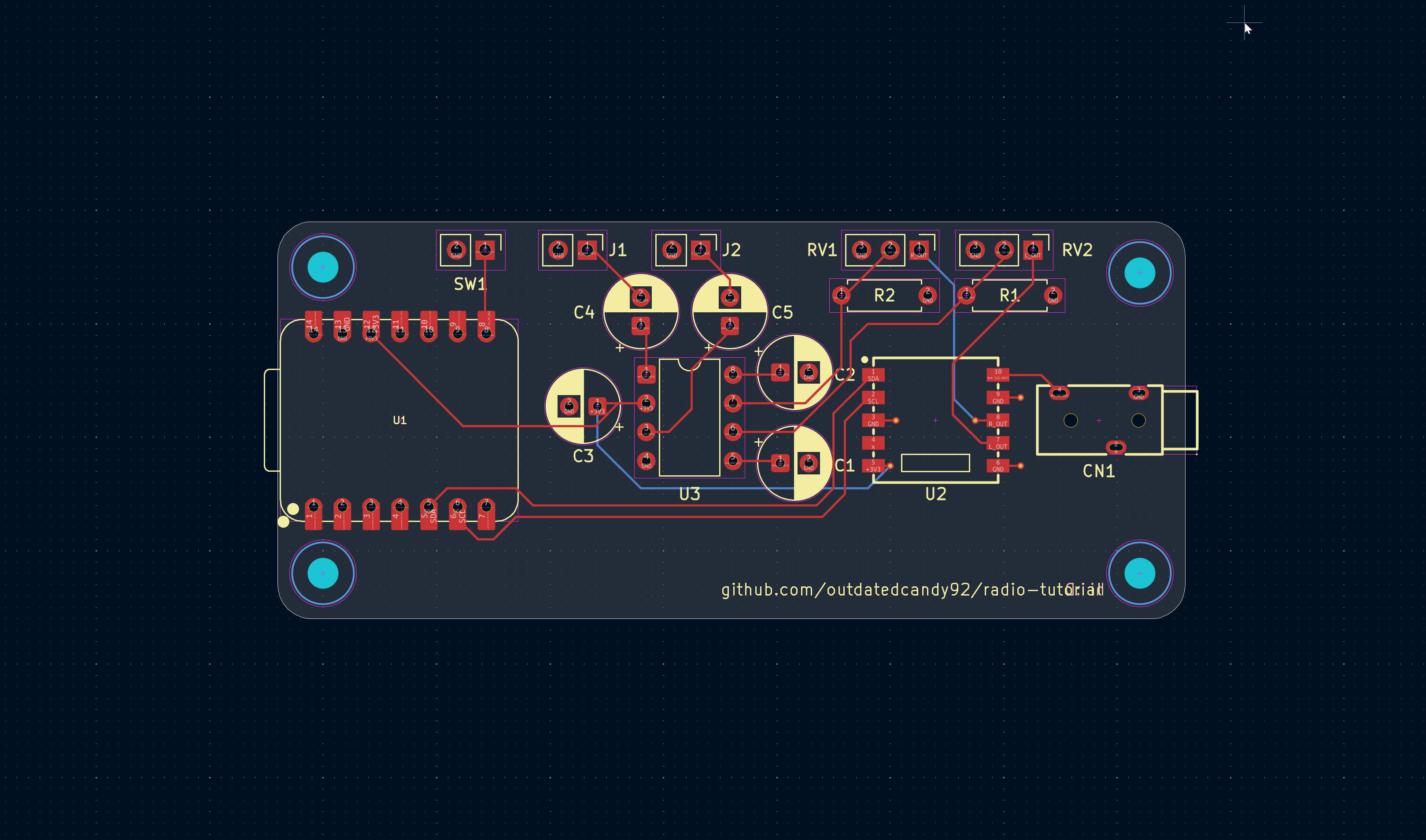
Radio Tutorial is an open-source printed circuit board by Outdatedcandy92, from the Outdatedcandy92/Radio-Tutorial repository on GitHub. It is a 2-layer board of 80 × 35 mm with 20 parts on 27 nets, routed with 72 tracks and 5 vias.
It is built around the TDA2822NBD and PJ-3200. Its parts include 5 capacitors, 3 ICs, 3 connectors, 2 resistors and 1 switch. It belongs with the radio and wireless and audio and music boards and the RP2040 boards of this library.
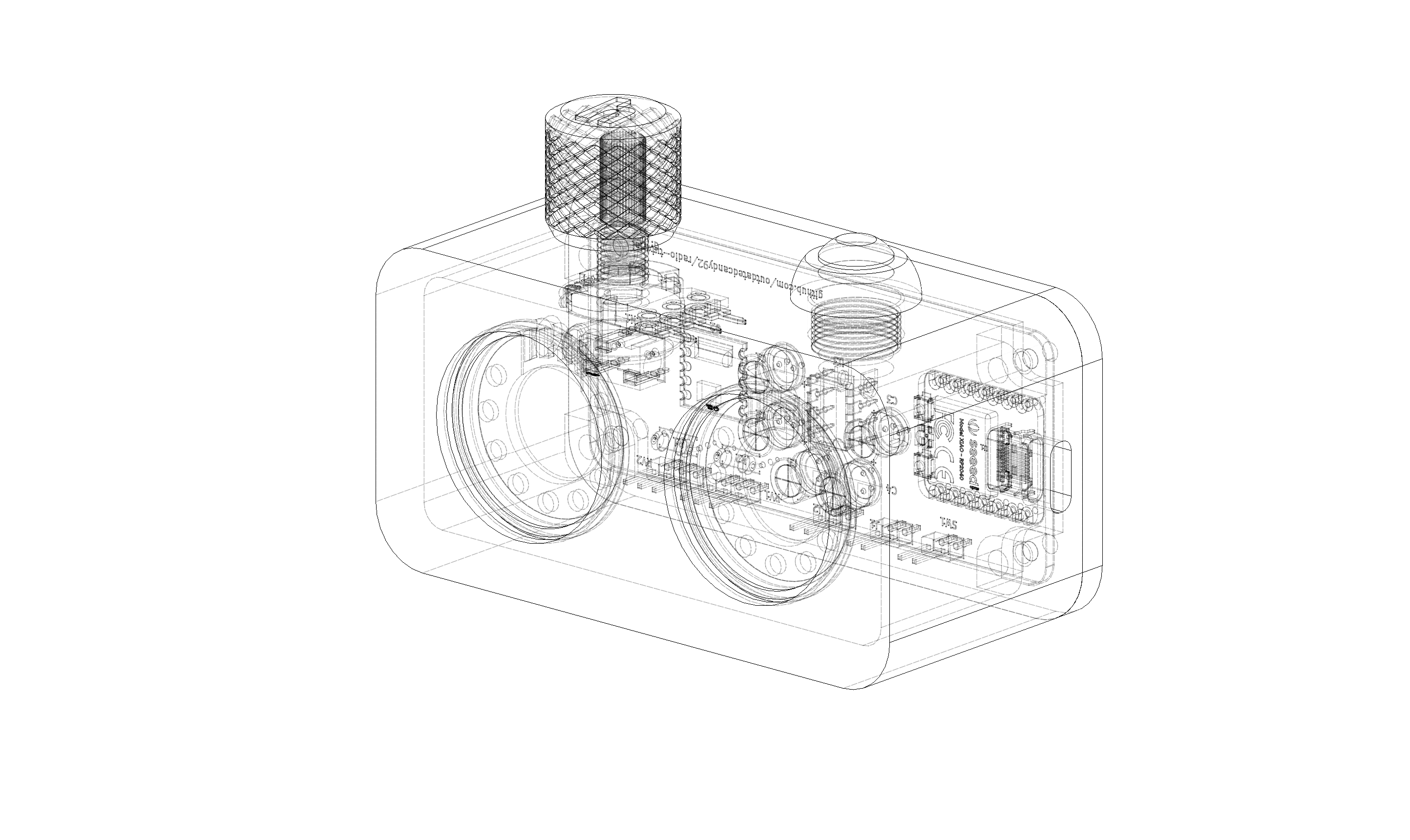
An FM receiver board built around the RDA5807 module. It includes a Seeed Xiao RP2040 to control the RDA5807 over I2C. The board also includes a TDA2822 audio amplifier, which allows you to connect and drive speakers directly from the board. The RDA5807's antenna input is connected to a 3.5mm jack, so you can plug in a 3.5mm antenna.
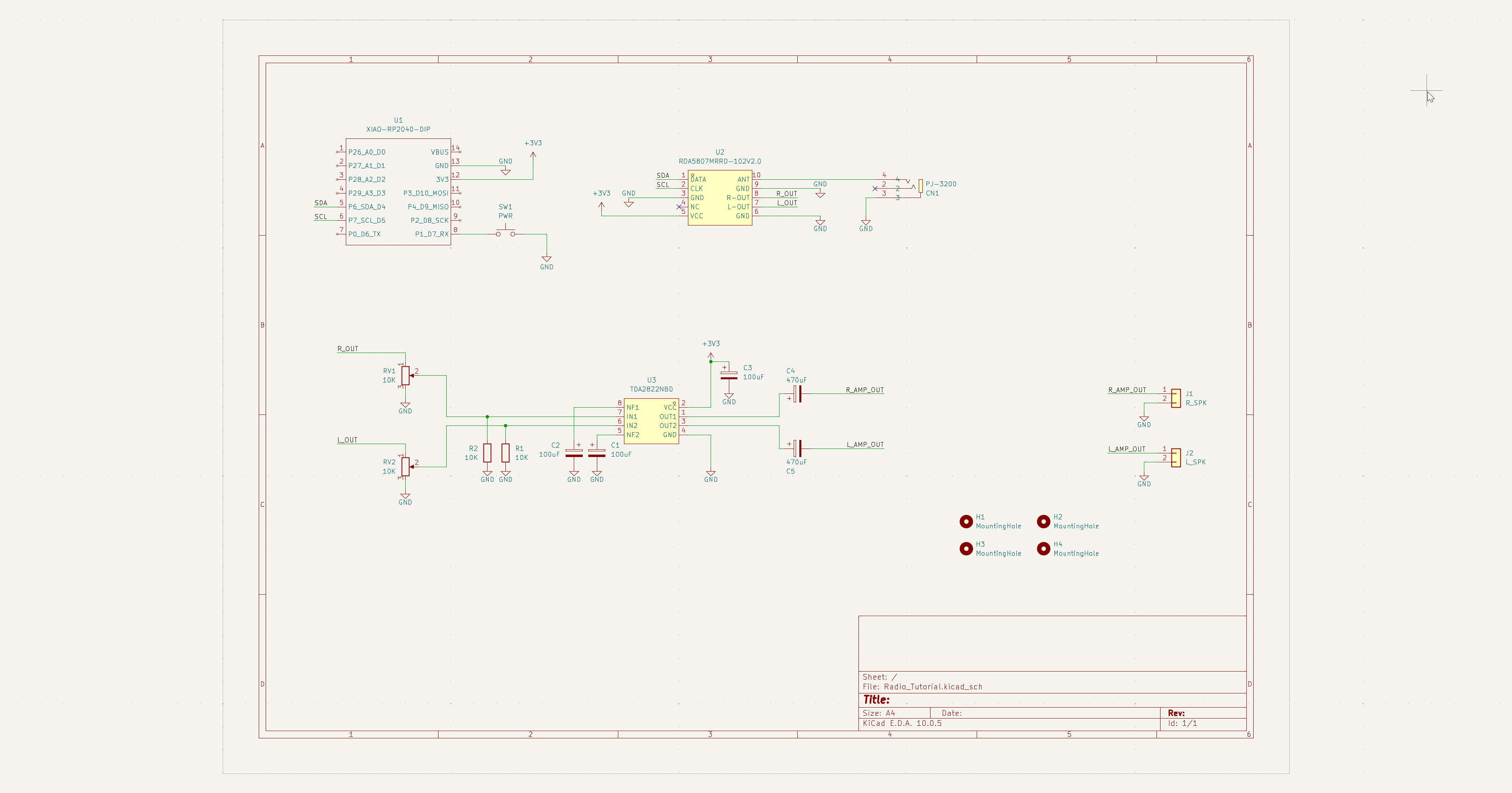
| Qty | Value | Footprint | References |
|---|---|---|---|
| 4 | MountingHole | MountingHole:MountingHole_2.7mm_M2.5 | H1, H2, H3, H4 |
| 3 | 100uF | Capacitor_THT:CP_Radial_D6.3mm_P2.50mm | C1, C2, C3 |
| 2 | 10K | Resistor_THT:R_Axial_DIN0207_L6.3mm_D2.5mm_P7.62mm_Horizontal | R1, R2 |
| 2 | 10K | Connector_PinHeader_2.54mm:PinHeader_1x03_P2.54mm_Vertical | RV1, RV2 |
| 2 | 470uF | Capacitor_THT:CP_Radial_D6.3mm_P2.50mm | C4, C5 |
| 1 | L_SPK | Connector_PinHeader_2.54mm:PinHeader_1x02_P2.54mm_Vertical | J2 |
| 1 | PJ-3200 | easyeda2kicad:AUDIO-TH_PJ-3200 | CN1 |
| 1 | PWR | Connector_PinHeader_2.54mm:PinHeader_1x02_P2.54mm_Vertical | SW1 |
| 1 | RDA5807MRRD-102V2.0 | Static:RDA5807 | U2 |
| 1 | R_SPK | Connector_PinHeader_2.54mm:PinHeader_1x02_P2.54mm_Vertical | J1 |
| 1 | TDA2822NBD | Package_DIP:DIP-8_W7.62mm | U3 |
| 1 | XIAO-RP2040-DIP | Static:XIAO-RP2040-DIP | U1 |
It measures 80 × 35 mm and has 2 copper layers, 1.6 mm thick.
20 parts, built around the TDA2822NBD and PJ-3200. The full list of its parts is on this page, with links to each part's symbol and footprint where PCBKit's library has them.
From the Outdatedcandy92/Radio-Tutorial repository on GitHub, at the commit this page was made from: the board is src/pcb/Radio_Tutorial.kicad_pcb and its schematic src/pcb/Radio_Tutorial.kicad_sch. PCBKit opens the board in the browser, with nothing to install.
Its repository states no licence, so its author keeps all rights: ask Outdatedcandy92 before reusing the design.


jibrilsharafi/EnergyMe-Home
Smart energy meter capable of monitoring up to 16 channels. Supports MQTT, REST API, Modbus TCP, InfluxDB, AWS IoT Core. Friendly UI and fully open source (PCB, schematics, components, source code)

OpenShock/Hardware
KiCAD files for PCBs for transmitters and other hardware for OpenShock.


akita11/SoundDropMiniUNIT
PC接続時に現れるドライブ内の"config.txt"で、以下の機能を指定できます。 設定情報は、config.txtの1行目に、以下の7桁の数値を記載します(それ以降は無視される)。 - 1文字目: ボタンの動作。0=再生中に中断可、1=再生中に中断不可、2=リピート再生1、3=リピート再生2、4=ON/OFF、5=常時リピート再生 - 2-3文字目: 音量(00-30) - 4文字目…
