4 layers58 × 40 mm

 opme/motor-driver
open source motor drivers to be driven by foc controller
Panel.opm inline is an open-source printed circuit board by opme, from the opme/motor-driver repository on GitHub. It is a 4-layer board of 249.8 × 250 mm with 2,473 parts on 1,344 nets, routed with 13,056 tracks and 4,440 vias.
It is built around the TMC6200-TA, HYG025N06LS1C2 and NUP4114UCW1T2G-N, with the WSD90P06DN56 among its other parts. Its parts include 624 capacitors, 600 resistors, 168 diodes, 168 transistors and 120 connectors. It belongs with the robots and motor control boards of this library.


This motor driver uses inline current sensing. The driver chip TMC6200 has built in current sensing.
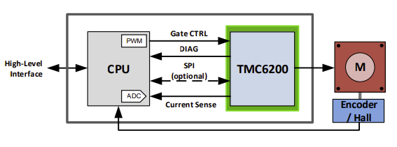
Design uses TMC6200 gate driver. The datasheet is located at . Below are some high level details about the gate driver.
Universal high voltage BLDC/PMSM/Servo MOSFET 3-halfbridge gate-driver with in line motor current sensing. External MOSFETs for up to 100A motor current. 3 Floating Sense Amplifiers with programmable gain (5, 10, 20)
Integrated current sense amplifiers eliminate costly sense amplifiers required for FOC controllers (recommended use for applications up to 10A, use external precision amplifiers for higher current with low sense resistor values)
THE TMC6200 OFFERS TWO BASIC MODES OF OPERATION:
MODE 1: Stand-alone driver with pin configuration Enable this mode by tying low pin SPE. The interface pins allow a number of different settings for BBM generation and sense amplifier amplification control.
MODE 2: SPI controlled This mode allows detailed control over the protection, diagnostic and control features, e.g. for tuning overcurrent detection. Enable this mode by tying high pin SPE.
The driver integrates a four-level temperature sensor (120°C pre-warning and selectable 136°C / 143°C / 150°C thermal shutdown)
The TMC6200 protects the MOSFET power stages against a short circuit or overload condition by monitoring the voltage drop in the high-side MOSFETs, as well as the voltage drop in the low-side mosfets
Choice is to run in Mode 1 - Stand-alone driver with pin configuration. See datasheet Figure 1.1 Standalone application using differential sensing. Existing FOC algorithms should run without relying on the SPI interface. Future versions could change if the controller firmware has a driver added for TMC6200.
In this mode the SPI pins are used for configuration and not settings/diagnostics. Setting SDO/Single to +VCC_IO allow signals to be set to DRV_EN. This is also the case for the Drive Strength and the sense amplication. In a 10A implementation we set sense amplification to 10 and 00 driver strength since we are using simialr mosfets that were tested in the datasheet.
Drive Strength: CSN / IDRV0 and SCK / IDRV1 - 00: 0.5A 01: 0.5/1A, 10: 1A, 11: 1.5A, currently set to 00 for .5A
Sense Amplification: SDI / AMPLx10 - Sense Amplification 0: 5, 1: 10, currently set to 10.
The TMC6200 IC current sensing is recommended to have a limit of 10A when using the internal sensing.
The thermal design of the PCB is also designed for 10A max current. The 10A limit is chosen to allow full SMT and single side hole through components with 1oz copper.
Heatsink over the gate driver and mosfets is required over a certain current. 28x28x20 is a standard heat sink size and is added to the pcb using silicon thermal glue.
Initial parts were selected based on the Trinamic reference designs that I have copied into this git repo.
Footprint for capacitors and resistors chosen as 0603 to make it easier to manufacture with low end SMD machines.
Parts are selected that are available in quantity from various resellers due to current chip shortage. Avoided any parts that were only available in small quantities or not in stock.
Sense resistor selection. TMC6200 datasheet specifies different sense resistor selection. Sense resistor of 005R0 with 10x amplification was selected for 15A max current 10A continuous.
In addition to the TMC6200 internal temperature sensor, there is a temperature sensor on the board. The analog temperature signal is sent out the controller.
Mosfet selection. Reference design has via for +VM connection through SMT pad. This limits the vendor ability to manufacture the board and increases cost due to those needed to be capped in the manufacturing process. Alternative is to put the via next to the SMT pad.
See TMC6200 datasheet for full documentation of pins. Below is specific decisions taken when choice was given.
CLK 24 pin on the TMC6200 is tied to GND using short wire for internal clock. This clock has accuracy of +-4%
Exposed die pad: Connect the exposed die pad to a GND plane. Provide as many as possible vias for heat transfer to GND plane. Reference design has via for GND connection through SMT pad. Since TMC chip will be manually added for first batch, these through hole vias were used. If those are done by SMT in the future then some other solution for tying the pad to GRD may be needed.
Mosfet pads go to +VM but do not use hole through vias. This limits the vendor ability to manufacture the board and increases cost due to those needed to be capped in the manufacturing process. Alternative is to put the via next to the SMT pad which is done in this design.
| Type | Designator | Footprint | Discussion |
|---|---|---|---|
| TerminalBlock_3_P5.08mm | U3 | Libraries:TerminalBlock_bornier-3_P5.08mm | Should support 18A to 20A max current though design current is 10A |
| 1nF/100V | C14 C12 C11 | Capacitor_SMD:C_0603_1608Metric | |
| TerminalBlock_2_P5.08mm | U2 | Libraries:TerminalBlock_bornier-2_P5.08mm | |
| 330uF/63V | C15 C16 | Capacitor_THT:C_Radial_D10.0mm_H20.0mm_P5.00mm | TMC6200 datasheet recommends 100uF of electroltyic capacitor for each amp of current expected. Total 660 uF for 10 Amps included. 10000 hour life, low impedance, low ESR, high ripple current rating |
| VCC_IO | J2 | Connector_JST:JST_PH_B2B-PH-K_1x02_P2.00mm_Vertical | |
| 1000R/1% | R19 R21 | Resistor_SMD:R_0603_1608Metric | |
| 19-217/GHC-YR1S2/3T | D1 D2 | LED_SMD:LED_0603_1608Metric | |
| 150R/1% | R20 | Resistor_SMD:R_0603_1608Metric | |
| 4700R/1% | R18 R17 R24 | Resistor_SMD:R_0603_1608Metric | |
| 10000R/1% | R16 | Resistor_SMD:R_0603_1608Metric | |
| 100nF/50V | C17 C20 C10 | Capacitor_SMD:C_0603_1608Metric | |
| Temperature | J5 | Connector_JST:JST_PH_B2B-PH-K_1x02_P2.00mm_Vertical | |
| PWMx6 | J3 | Connector_JST:JST_PH_B6B-PH-K_1x06_P2.00mm_Vertical | |
| 0R | R22 | Resistor_SMD:R_0603_1608Metric | |
| 1500R/1% | R23 | Resistor_SMD:R_0603_1608Metric | |
| Current Sensing | J6 | Connector_JST:JST_PH_B3B-PH-K_1x03_P2.00mm_Vertical | |
| SPI/Info | J1 | Connector_JST:JST_PH_B6B-PH-K_1x06_P2.00mm_Vertical | |
| 0R | R26 | Resistor_SMD:R_0603_1608Metric | |
| 0Ω | R25 | Resistor_SMD:R_0603_1608Metric | |
| 2.2uF/50V | C13 C19 | Capacitor_SMD:C_0805_2012Metric | |
| 100nF/100V | C18 | Capacitor_SMD:C_0805_2012Metric | |
| TMC6200-TA | IC1 | Libraries:TMC6200-TA | |
| 2R2/1% | R4 R6 R11 R13 R3 R1 | Resistor_SMD:R_0603_1608Metric | slope control resistors. 1Ohm to 2.2Ohm recommended for larger MOSFETs. |
| 10R/1% | R5 R12 R2 | Resistor_SMD:R_0603_1608Metric | |
| 0R005/1%/1W | R9 R10 R14 R15 R7 R8 | Resistor_SMD:R_1206_3216Metric | Use low inductivity SMD type, e.g. 1210 or 2512 resistor for RS |
| 4.7uF/100V | C8 C9 C7 | Capacitor_SMD:C_1210_3225Metric | |
| 4.7uF/16V | C5 C4 C6 | Capacitor_SMD:C_0603_1608Metric | Bootstrap capacitors. for larger QG - use minimum 4.7µF on 12VOUT pin. QG is 59.5nC at VDS=48V, VGS=10V, ID=20A |
| 22nF/100V | C1 | Capacitor_SMD:C_0603_1608Metric | |
| 100nF/100V | C2 C3 | Capacitor_SMD:C_0603_1608Metric | |
| Power Mosfet 60V 100A 2.5 max Rds(on) | Q2 Q6 Q4 Q3 Q1 Q5 | Libraries:PDFN-8 | HYG025N06LS1C2, 60V minimum, 2.5ohm max Rds(on) and fast switching for lower heat dissipation, Max current > 30A |
| Qty | Value | Footprint | References |
|---|---|---|---|
| 216 | 1uF/100V | Capacitor_SMD:C_0805_2012Metric | C21, C21, C21, C21, C21, C21, C21, C21, C21, C21, C21, C21, C21, C21, C21, C21 +200 |
| 144 | 0R005/1%/1W | Resistor_SMD:R_1206_3216Metric | R10, R10, R10, R10, R10, R10, R10, R10, R10, R10, R10, R10, R10, R10, R10, R10 +128 |
| 144 | 2R2/1% | Resistor_SMD:R_0603_1608Metric | R1, R1, R1, R1, R1, R1, R1, R1, R1, R1, R1, R1, R1, R1, R1, R1 +128 |
| 144 | HYG025N06LS1C2 | Libraries:PDFN-8 | Q1, Q1, Q1, Q1, Q1, Q1, Q1, Q1, Q1, Q1, Q1, Q1, Q1, Q1, Q1, Q1 +128 |
| 72 | 100nF/50V | Capacitor_SMD:C_0603_1608Metric | C10, C10, C10, C10, C10, C10, C10, C10, C10, C10, C10, C10, C10, C10, C10, C10 +56 |
| 72 | 10R/1% | Resistor_SMD:R_0603_1608Metric | R12, R12, R12, R12, R12, R12, R12, R12, R12, R12, R12, R12, R12, R12, R12, R12 +56 |
| 72 | 1nF/100V | Capacitor_SMD:C_0603_1608Metric | C11, C11, C11, C11, C11, C11, C11, C11, C11, C11, C11, C11, C11, C11, C11, C11 +56 |
| 72 | NUP4114UCW1T2G | Libraries:NUP4114UCW1T2G | D3, D3, D3, D3, D3, D3, D3, D3, D3, D3, D3, D3, D3, D3, D3, D3 +56 |
| 48 | 0R | Resistor_SMD:R_0603_1608Metric | R22, R22, R22, R22, R22, R22, R22, R22, R22, R22, R22, R22, R22, R22, R22, R22 +32 |
| 48 | 1000R/1% | Resistor_SMD:R_0603_1608Metric | R19, R19, R19, R19, R19, R19, R19, R19, R19, R19, R19, R19, R19, R19, R19, R19 +32 |
| 48 | 100nF/100V | Capacitor_SMD:C_0603_1608Metric | C2, C2, C2, C2, C2, C2, C2, C2, C2, C2, C2, C2, C2, C2, C2, C2 +32 |
| 48 | 2.2uF/50V | Capacitor_SMD:C_0805_2012Metric | C13, C13, C13, C13, C13, C13, C13, C13, C13, C13, C13, C13, C13, C13, C13, C13 +32 |
| 48 | 330uF/63V | Capacitor_THT:C_Radial_D10.0mm_H20.0mm_P5.00mm | C15, C15, C15, C15, C15, C15, C15, C15, C15, C15, C15, C15, C15, C15, C15, C15 +32 |
| 48 | 4.7UF/16V | Capacitor_SMD:C_0603_1608Metric | C5, C5, C5, C5, C5, C5, C5, C5, C5, C5, C5, C5, C5, C5, C5, C5 +32 |
| 48 | 4700R/1% | Resistor_SMD:R_0603_1608Metric | R17, R17, R17, R17, R17, R17, R17, R17, R17, R17, R17, R17, R17, R17, R17, R17 +32 |
| 48 | MountingHole | MountingHole:MountingHole_2.2mm_M2_Pad_Via | H201, H201, H201, H201, H201, H201, H201, H201, H201, H201, H201, H201, H201, H201, H201, H201 +32 |
| 24 | 0Ω | Resistor_SMD:R_0603_1608Metric | R25, R25, R25, R25, R25, R25, R25, R25, R25, R25, R25, R25, R25, R25, R25, R25 +8 |
| 24 | 10000R/1% | Resistor_SMD:R_0603_1608Metric | R16, R16, R16, R16, R16, R16, R16, R16, R16, R16, R16, R16, R16, R16, R16, R16 +8 |
| 24 | 100KR | Resistor_SMD:R_0603_1608Metric | R27, R27, R27, R27, R27, R27, R27, R27, R27, R27, R27, R27, R27, R27, R27, R27 +8 |
| 24 | 100nF/100V | Capacitor_SMD:C_0805_2012Metric | C18, C18, C18, C18, C18, C18, C18, C18, C18, C18, C18, C18, C18, C18, C18, C18 +8 |
| 24 | 10V | Diode_SMD:D_SOD-123 | D4, D4, D4, D4, D4, D4, D4, D4, D4, D4, D4, D4, D4, D4, D4, D4 +8 |
| 24 | 150R/1% | Resistor_SMD:R_0603_1608Metric | R20, R20, R20, R20, R20, R20, R20, R20, R20, R20, R20, R20, R20, R20, R20, R20 +8 |
| 24 | 22nF/100V | Capacitor_SMD:C_0603_1608Metric | C1, C1, C1, C1, C1, C1, C1, C1, C1, C1, C1, C1, C1, C1, C1, C1 +8 |
| 24 | 4.7uF/16V | Capacitor_SMD:C_0603_1608Metric | C4, C4, C4, C4, C4, C4, C4, C4, C4, C4, C4, C4, C4, C4, C4, C4 +8 |
| 24 | Current Sensing | Connector_JST:JST_PH_B3B-PH-K_1x03_P2.00mm_Vertical | J6, J6, J6, J6, J6, J6, J6, J6, J6, J6, J6, J6, J6, J6, J6, J6 +8 |
| 24 | Fan | Connector_JST:JST_PH_B2B-PH-K_1x02_P2.00mm_Vertical | J4, J4, J4, J4, J4, J4, J4, J4, J4, J4, J4, J4, J4, J4, J4, J4 +8 |
| 24 | Green LED | LED_SMD:LED_0603_1608Metric | D1, D1, D1, D1, D1, D1, D1, D1, D1, D1, D1, D1, D1, D1, D1, D1 +8 |
| 24 | Heatsink | Symbol:OSHW-Logo2_7.3x6mm_SilkScreen | HS1, HS1, HS1, HS1, HS1, HS1, HS1, HS1, HS1, HS1, HS1, HS1, HS1, HS1, HS1, HS1 +8 |
| 24 | Info | Connector_JST:JST_PH_B3B-PH-K_1x03_P2.00mm_Vertical | J1, J1, J1, J1, J1, J1, J1, J1, J1, J1, J1, J1, J1, J1, J1, J1 +8 |
| 24 | PWMx6 | Connector_JST:JST_PH_B6B-PH-K_1x06_P2.00mm_Vertical | J3, J3, J3, J3, J3, J3, J3, J3, J3, J3, J3, J3, J3, J3, J3, J3 +8 |
| 24 | Red LED | LED_SMD:LED_0603_1608Metric | D2, D2, D2, D2, D2, D2, D2, D2, D2, D2, D2, D2, D2, D2, D2, D2 +8 |
| 24 | TMC6200-TA | Libraries:TMC6200-TA | IC1, IC1, IC1, IC1, IC1, IC1, IC1, IC1, IC1, IC1, IC1, IC1, IC1, IC1, IC1, IC1 +8 |
| 24 | TVS DIODE | Diode_SMD:D_SMA | D6, D6, D6, D6, D6, D6, D6, D6, D6, D6, D6, D6, D6, D6, D6, D6 +8 |
| 24 | TerminalBlock_2_P5.08mm | Libraries:TerminalBlock_bornier-2_P5.08mm | U2, U2, U2, U2, U2, U2, U2, U2, U2, U2, U2, U2, U2, U2, U2, U2 +8 |
| 24 | TerminalBlock_3_P5.08mm | Libraries:TerminalBlock_bornier-3_P5.08mm | U3, U3, U3, U3, U3, U3, U3, U3, U3, U3, U3, U3, U3, U3, U3, U3 +8 |
| 24 | VCC_IO | Connector_JST:JST_PH_B2B-PH-K_1x02_P2.00mm_Vertical | J2, J2, J2, J2, J2, J2, J2, J2, J2, J2, J2, J2, J2, J2, J2, J2 +8 |
| 24 | WSD90P06DN56 | Libraries:PDFN-8 | Q7, Q7, Q7, Q7, Q7, Q7, Q7, Q7, Q7, Q7, Q7, Q7, Q7, Q7, Q7, Q7 +8 |
The 1,824 most common of 2,473 parts.
It measures 249.8 × 250 mm and has 4 copper layers, 1.6 mm thick.
2,473 parts, built around the TMC6200-TA, HYG025N06LS1C2, NUP4114UCW1T2G-N and WSD90P06DN56. The full list of its parts is on this page, with links to each part's symbol and footprint where PCBKit's library has them.
From the opme/motor-driver repository on GitHub, at the commit this page was made from: the board is opm-inline-mcu/panel.opm-inline.kicad_pcb and its schematic opm-inline-mcu/source/Connectors.kicad_sch. PCBKit opens the board in the browser, with nothing to install.
Its repository states no licence, so its author keeps all rights: ask opme before reusing the design.


halworsen/tdt4295-grafikk
Bugge is an embedded system designed from absolute scratch, and is capable of drawing arbitrarily complex 3D wireframe models with VGA output.

neurobot-1000/neurobot-1000.github.io
Monorepo for the Neurobot-1000 works

Ryan-Fagan/QuadcopterPCB
Gerbers, models, & code for an STM32 quadcopter focused on reasearch applications.

ClemensElflein/xESC
The xESC is an easy to use, low cost electronic speed controller (ESC) design for sensored brushless DC (BLDC) motors.

dognotdog/smol_servo
circuitry and software for controlling NEMA17 size brushless motors and stepper motors as servos.

YaseenTwati/ThunderMini
A modular, stackable brushless motor driver platform based on the TMC6200, TMC4671, and STM32G473.

