Skip to the content
PCBKitNew board
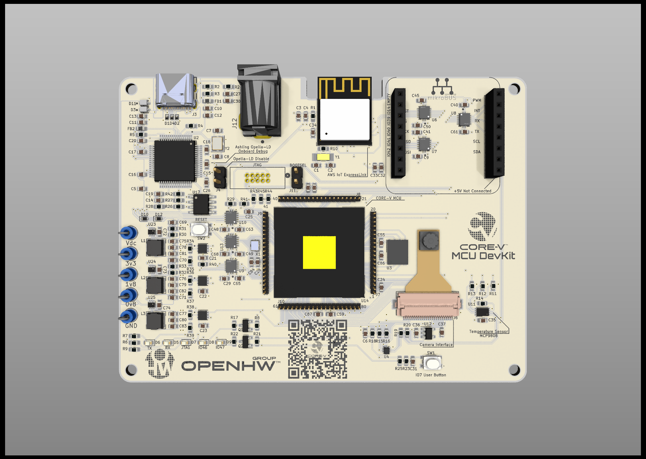
4 layers100 × 75 mmOpenHW DevKit, the printed circuit board in 3D

This is the CORE-V MCU DevKit project, hosting the open-source artifacts for the CORE-V MCU Development Kit.

Size
100 × 75 mm
Copper layers
4
Thickness
1.6 mm
Parts
235
Nets
217
Pads
1,007
Tracks, vias
1,714, 286
Pours
8
Routed
Yes
KiCad
KiCad 7 (file 20221018)
Created
10 Mar 2022
Updated
31 Jan 2024

Overview

OpenHW DevKit is an open-source printed circuit board by openhwfoundation, from the openhwfoundation/core-v-mcu-devkit repository on GitHub. It is a 4-layer board of 100 × 75 mm with 235 parts on 217 nets, routed with 1,714 tracks and 286 vias.

It is built around the ESP32-C3-MINI-1, FT2232HL-REEL and MCP9808-E/MS, with the W25Q32JWZPIQ, MP6400DG-01-LF-Z and AMS1117-3.3 among its other parts. Its parts include 54 capacitors, 41 resistors, 20 ICs, 13 connectors and 12 diodes. It belongs with the interfaces and adapters boards and the ESP32 and RISC-V boards of this library.

Main components

12

README

README.md

core-v-mcu-devkit

The CORE-V MCU DevKit is an evaluation platform for the OpenHW RISC-V CV32E40P core IP (v1.0.0). More information can be found at the CV32E40P repo.

Organization

  1. Project Parts - parts not built into kicad required for the devkit
  2. kicad - kicad schematics and pcb files
  3. images - image files to support this document

About the devkit

This devkit has the following features:

  1. CORE-V MCU (including CV32E40P (v1.0.0) RISC-V core and Quicklogic ArcticPro2 Embedded FPGA)
  2. 4MB Flash memory to hold programs and EFPGA bit images
  3. Onboard Ashling Opella LD JTAG debugger + Serial Consol interface
  4. Offboard JTAG Connector
  5. Every signal of the MCU brought out to test pins
  6. I2C temperature sensor
  7. CSI Camera interface with Himax camera
  8. 2 LED's controllable by the MCU or by the EFPGA
  9. 1 button for input to the MCU or to the FPGA
  10. mikroBUS socket for system expansion
  11. Espressif AWS IoT ExpressLink interface for cloud learning

devkit image

PDF Schematic

Power

The devkit can be powered from 5 - 18V. This can be easily accomplished via the 2.1mm DC barrel jack. The USB-C connector will negotiate 5v from the USB source.

Voltage levels

The CORE-V-MCU has a 1.8v I/O pad ring. The 3.3v peripherals are interfaced to the 1.8v MCU with 7 level shifters. The pins directly around the MCU are connected directly to the MCU pads and will be 1.8v logic. The QSPI program flash memory is also at 1.8v logic. The JTAG interface to the Ashling Opella LD is level shifted. The enable signals on the JTAG level shifters is connected to jumper J4. Inserting a jumper will disable the level shifters to the on-board JTAG interface allowing the JTAG header to be used.

Note: the JTAG header is directly connected to the CORE-V-MCU and will require 1.8v logic.

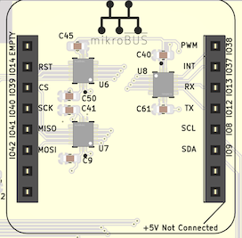
mikroBUS

The microBUS header provides a UART, GPIO, I2C and SPI interface. The UART interface is shared with the AWS IoT ExpressLink. The CORE-V-MCU has an I/O multiplexer and an alternate pin mode allows the UART interface to be switched between two sets of I/O pins. The microBUS is fully wired except for the 5v power option. 5v is not available to microBUS so ensure any CLICK's are configured for 3.3v. microbus connector

Parts

235
QtyValueFootprintReferences
63TestPoint_SmallTestPoint:TestPoint_Pad_D1.0mmTP10, TP11, TP12, TP13, TP14, TP15, TP16, TP17, TP18, TP19, TP25, TP27, TP28, TP29, TP30, TP31 +47
33100nFCapacitor_SMD:C_0603_1608MetricC4, C12, C13, C14, C15, C16, C17, C18, C19, C20, C28, C29, C31, C34, C40, C41 +17
710kResistor_SMD:R_0603_1608MetricR35, R37, R39, R41, R43, R44, R45
64.7kResistor_SMD:R_0603_1608MetricR15, R16, R19, R20, R25, R40
6NTB0104BQ,115NTB0104:NXP_Semiconductors-SOT762-1-08_2019-0-MFGU6, U7, U8, U9, U10, U13
6SolderJumper_2_BridgedJumper:SolderJumper-2_P1.3mm_Bridged_RoundedPad1.0x1.5mmJP1, JP2, JP6, JP7, JP8, JP9
510kResistor_SMD:R_0603_1608Metric_Pad0.98x0.95mm_HandSolderR1, R27, R28, R29, R42
410uFCapacitor_SMD:C_0603_1608MetricC3, C5, C33, C69
412.5pFCapacitor_SMD:C_0603_1608MetricC1, C2, C7, C8
41uFCapacitor_SMD:C_0603_1608MetricC24, C36, C37, C82
42.2kResistor_SMD:R_0603_1608Metric_Pad0.98x0.95mm_HandSolderR6, R7, R9, R26
447kResistor_SMD:R_0603_1608MetricR11, R12, R13, R14
4Conn_01x20Connector_PinHeader_1.00mm:PinHeader_1x20_P1.00mm_VerticalJ7, J8, J9, J10
4MountingHoleMountingHole:MountingHole_2.7mm_M2.5H1, H2, H3, H4
3150pFCapacitor_SMD:C_0603_1608MetricC21, C22, C23
35.1kResistor_SMD:R_0603_1608Metric_Pad0.98x0.95mm_HandSolderR2, R3, R5
3ESD9B5.0ST5GDiode_SMD:D_SOD-923D1, D2, D4
3LED_SmallLED_SMD:LED_0603_1608MetricD5, D6, D7
3MP6400DG-01-LF-ZMP6400:QFN6_MP6400_MNPU5, U15, U16
3SolderJumper_2_OpenJumper:SolderJumper-2_P1.3mm_Open_RoundedPad1.0x1.5mmJP3, JP4, JP5
2100nCapacitor_SMD:C_0603_1608MetricC32, C35
21N914WTDiode_SMD:D_SOD-523D10, D12
21kResistor_SMD:R_0603_1608MetricR8, R21
2220Resistor_SMD:R_0603_1608MetricR17, R22
24.7uFCapacitor_SMD:C_0603_1608MetricC10, C11
2BAT760-7diode:Diodes-SOD323-03_2017-0-0D3, D11
2Conn_01x02_MaleConnector_PinHeader_2.54mm:PinHeader_1x02_P2.54mm_VerticalJ4, J11
2Ferrite_Bead_SmallInductor_SMD:L_0603_1608Metric_Pad1.05x0.95mm_HandSolderFB1, FB2
2LEDLED_SMD:LED_0603_1608MetricD8, D9
2MMBT3904Package_TO_SOT_SMD:SOT-23Q1, Q2
2SW_PushButton:TS204225WT160SMTTRSW1, SW2
10v8TestPoint:TestPoint_Loop_D2.54mm_Drill1.5mm_BeadedTP5
1100Resistor_SMD:R_0603_1608MetricR23
1100kResistor_SMD:R_0603_1608MetricR24
112MHzCrystal:Crystal_SMD_Abracon_ABM8G-4Pin_3.2x2.5mmY2
112kResistor_SMD:R_0603_1608Metric_Pad0.98x0.95mm_HandSolderR4
11MResistor_SMD:R_0603_1608Metric_Pad0.98x0.95mm_HandSolderR10
11v8TestPoint:TestPoint_Loop_D2.54mm_Drill1.5mm_BeadedTP4
1200kResistor_SMD:R_0603_1608MetricR18
122uFCapacitor_SMD:C_0603_1608MetricC81
13.3uFCapacitor_SMD:C_0603_1608MetricC26
132.5kResistor_SMD:R_0603_1608MetricR36
132.768kHzCrystal:Crystal_SMD_MicroCrystal_CC7V-T1A-2Pin_3.2x1.5mm_HandSolderingY1
13220-10-0100-00jtag:CONN_3220-10-0100-00_CNCJ5
13v3TestPoint:TestPoint_Loop_D2.54mm_Drill1.5mm_BeadedTP3
165kResistor_SMD:R_0603_1608MetricR34
17.5kResistor_SMD:R_0603_1608MetricR38
193C56Package_SO:SOIC-8_3.9x4.9mm_P1.27mmU17
1AMS1117-3.3Package_TO_SOT_SMD:SOT-223-3_TabPin2U18
1AP2127K-1.8Package_TO_SOT_SMD:SOT-23-5U19
1AP2127K-2.8Package_TO_SOT_SMD:SOT-23-5U12
1AP2127K-ADJPackage_TO_SOT_SMD:SOT-23-5U20
1CORE-V-MCUcore-v:BGA-80-22x22U14
1Conn_01x24Connector_FFC-FPC:Hirose_FH12-24S-0.5SH_1x24-1MP_P0.50mm_HorizontalJ6
1Conn_02x03_Odd_EvenConnector_PinHeader_1.27mm:PinHeader_2x03_P1.27mm_Vertical_SMDJ2
1Conn_02x05_Odd_EvenConnector_PinHeader_1.27mm:PinHeader_2x05_P1.27mm_Vertical_SMDJ1
1ECS-2520MVLC-100-CNOscillator:Oscillator_SMD_ECS_2520MV-xxx-xx-4Pin_2.5x2.0mmX1
1ESP32-C3-MINI-1espressif:ESP32-C3-MINI-1U1
1FT2232HL-REELft2232:QFP50P1200X1200X160-64NU2
1FXMA2102UMXFXMA2102UMX:FXMA2102UMXU4
1GNDTestPoint:TestPoint_Loop_D2.54mm_Drill1.5mm_BeadedTP6
1LOGOlogos:core-vG***
1LOGOlogos:mcu_devkit_bold_275_reverseG***
1LOGOlogos:openhw_group_smallG***
1MCP9808Package_DFN_QFN:DFN-8-1EP_3x2mm_P0.5mm_EP1.7x1.4mmU11
1MIKROBUS_HOST_CONNmikroBus:MIKROBUS_HOST_CONNCON1
1PJ-002Bbarrel:CUI_PJ-002BJ12
1TestPointTestPoint:TestPoint_Pad_D1.0mmTP1
1USB4105-GF-Ausb:GCT_USB4105-GF-AJ3
1VdcTestPoint:TestPoint_Loop_D2.54mm_Drill1.5mm_BeadedTP2
1W25Q32JWZPPackage_SON:WSON-8-1EP_6x5mm_P1.27mm_EP3.4x4.3mmU3
1~logos:devkits_qrQR-Code1

Questions

How big is the OpenHW DevKit PCB?

It measures 100 × 75 mm and has 4 copper layers, 1.6 mm thick.

What parts does the OpenHW DevKit use?

235 parts, built around the ESP32-C3-MINI-1, FT2232HL-REEL, MCP9808-E/MS and W25Q32JWZPIQ. The full list of its parts is on this page, with links to each part's symbol and footprint where PCBKit's library has them.

Where can I download the OpenHW DevKit KiCad files?

From the openhwfoundation/core-v-mcu-devkit repository on GitHub, at the commit this page was made from: the board is kicad/OpenHW DevKit.kicad_pcb and its schematic kicad/OpenHW DevKit.kicad_sch. PCBKit opens the board in the browser, with nothing to install.

Can I use the OpenHW DevKit design in my own project?

Its repository states no licence, so its author keeps all rights: ask openhwfoundation before reusing the design.

Similar boards

  • 4 layers18 × 29 mmEsp32c6-pico, the printed circuit board in 3D

    Esp32c6-pico

    TreeNewbeer/esp32c6-pico

    2026-09-11 第一版 PCB 提交快照:保留用户在居中后对 R19、R15、局部短线及图形的继续调整;R19 / R15 当前坐标为 (115.70, 120.40) / (115.70, 122.36) mm。已重新填铜并同步贴装坐标、二维预览和报告,ERC 0、DRC 错误 0 / 丝印警告 1、未连接 0、一致性问题 0,QA 39/53。见 当前提交记录。以下居中对比及旧 3D 图保留为历史记录。

    59 parts
  • 4 layers39 × 54 mmCaravel mvp, the printed circuit board in 3D

    Caravel mvp

    TinyTapeout/caravel-mvp-pcb

    the minimum necessary to use a Caravel chip (Google MPW or chipIgnite)

    58 parts8Apache-2.0
  • 4 layers66.5 × 45.7 mmTip top, the printed circuit board in 3D

    Tip top

    psychogenic/asic-necklace-pcbs

    Schems and PCBs for Matt's awesome ASIC necklace, in collaboration with Adam Zeloof

    93 parts2
  • 2 layers27.8 × 56 mmESP32, the printed circuit board in 3D

    ESP32

    leoagea/ESP32_Board

    Homemade board with ESP32

    36 parts
  • 2 layers70 × 30.4 mmPlato B1, the printed circuit board in 3D

    Plato B1

    koopero/Plato

    PlatoA1 is a regular triangle, made of light and plastic, with a dimension of about an inch. This subassembly is meant as an experiment in:

    52 parts
  • 2 layers62.3 × 65 mmNixie hvdc, the printed circuit board in 3D

    Nixie hvdc

    YashKarthik/nixie-hvdc

    boost converter for nixie tube power supply

    44 parts1
  • 4 layers79.6 × 92.5 mmWCS1700-Calibrator, the printed circuit board in 3D

    WCS1700-Calibrator

    ekatynski/WCS1700-Calibrator

    A board designed to aid in calibrating six Winson WCS1700 hall effect sensors a the same time.

    120 parts
  • 2 layers85.7 × 54.4 mmArdutester, the printed circuit board in 3D

    Ardutester

    FranTerrassa/Ardutester

    Aparato a base de arduino para comprobar estado de componentes electrónicos

    17 parts