4 layers114.6 × 70.2 mm
Panelized-4layer
openconcepts-ar/accel2d
This project aims to provide a graphics server system based on hardware accelerated graphics, and a easy way to develop the graphics primitives.
470 parts1

 openconcepts-ar/accel2d1
This project aims to provide a graphics server system based on hardware accelerated graphics, and a easy way to develop the graphics primitives.
Panelized-6layer is an open-source printed circuit board by openconcepts-ar, from the openconcepts-ar/accel2d repository on GitHub. It is a 6-layer board of 70 × 53.6 mm with 318 parts on 170 nets, routed with 13,956 tracks and 828 vias.
It is built around the LFE5U-85F-8MG285I, TLV62569APDRL and W25Q128JVPIQ, with the TF-018, EA3036CQBR and TPS51206DSQR among its other parts. Its parts include 146 capacitors, 68 resistors, 16 connectors, 12 ICs and 8 inductors. It belongs with the FPGA and CPLD boards of this library.


This project aims to provide a graphics server system based on hardware accelerated graphics, and a easy way to develop the graphics primitives. The accelerated versions runs faster using the exact same C code as the software version by automatic translation (transpiling) to Verilog code.
As an example, let's see how to use and develop drawing privimites for solid rectangles and ellipses.
Ellipse case (see ellipse_fill32.cc file):
MODULE ellipse_fill32(
  bus_master(bus),
  const uint16&	x0,
  const uint16&	x1,
  const uint16&	y0,
  const uint16&	y1,
  const uint32&	rgba, //color
  const uint32& base, //pixel offset
  const int16& xstride, //normally 1, but can run backwards
  const int16& ystride //bytes to skip for next line (usually the framebuffer width * 4 bytes)
  )
The bus argument is automatically handled both in software and in hardware by privided macros.
The rectangle primitive follows the same function signature.
You can directly call the function using compilation with a normal C compiler:
ellipse_fill32(BUSMASTER_ARG, x0, x1, y0, y1, rgba, base, xstride, ystride);The BUSMASTER_ARG macro is an automatic argument, defined on a provided header file. It's useful for the implementation of the hardware accelerated primitive, as explained in the next section.
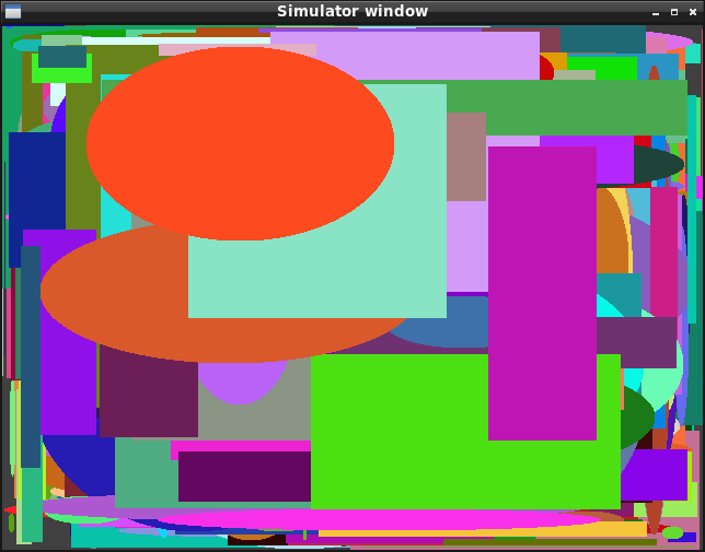
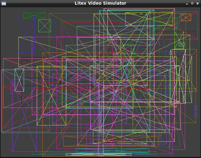
The following image is produced by the simulator by calling 1000 times to the software implementation of the primitives, using random coordinates:
To target hardware implementation on a FPGA, a Verilog file is automatically generated from from the corresponding C file having the drawing primitive algorithm, by using the following external tools: CflexHDL and the Silice transpilers (see Makefile.common target "c2v" for the invocation command details). Since this project aims to be transpiler-agnostic, the PipelineC transpiler is planned for a future version.
See a portion of the generated Verilog code, where part of the C expressions and interactions with the memory bus can be readily appreciated:
4: begin
    if (_q_x<_q_rw) begin
        _t_xx = _q_x*_q_x;
        _t_xh = (_t_xx)*(_q_hh);
        if (_t_xh+_q_yw<_q_wh) begin
            _d_bus_dat_w = in_rgba;
            _d_bus_we = 1;
            _d_bus_stb = 1;
            _d_bus_cyc = 1;
            if (!((_d_bus_stb&&_d_bus_we)&&!(_d_bus_stb&&in_bus_ack&&_d_bus_we))) begin
                _d_bus_stb = 0;
                _d_bus_adr = (_q_bus_adr+(in_xstride));
                _d_x = _q_x+1;
            end
        end else begin
            _d_bus_adr = (_q_bus_adr+(in_xstride));
            _d_x = _q_x+1;
        end
        _d__idx_fsm0 = 4;
    end else begin
        _d__idx_fsm0 = 5;
    end
end
After generating a System On Chip (SoC) for the target FPGA using the LiteX framework and a provided script, that includes the generated verilog files, the accelerator can be called as follows:
regs->x0 = x0;
regs->x1 = x1;
regs->y0 = y0;
regs->y1 = y1;
regs->base = VIDEO_FRAMEBUFFER_BASE + y0*FRAME_PITCH + x0*sizeof(rgba);
regs->xstride = SDRAM_BUS_BITS/8;
regs->ystride = FRAME_PITCH;
regs->rgba = rgba;

regs->run = 1; //start
while(!regs->done); //wait until done
As seen, you first set memory mapped registers with the desired values, then you start the core, then wait until the done flag is set.
Each accelerator core gets mapped starting at a fixed address (default 0x80000000 for the first accelerator, 0x80000800 for the second and so on, as provided by the correspoding macros). A C structure with the layout of registers is conveniently provided too (each register is 32-bit aligned, even if smaller).
The resulting execution in hardware is as follows:
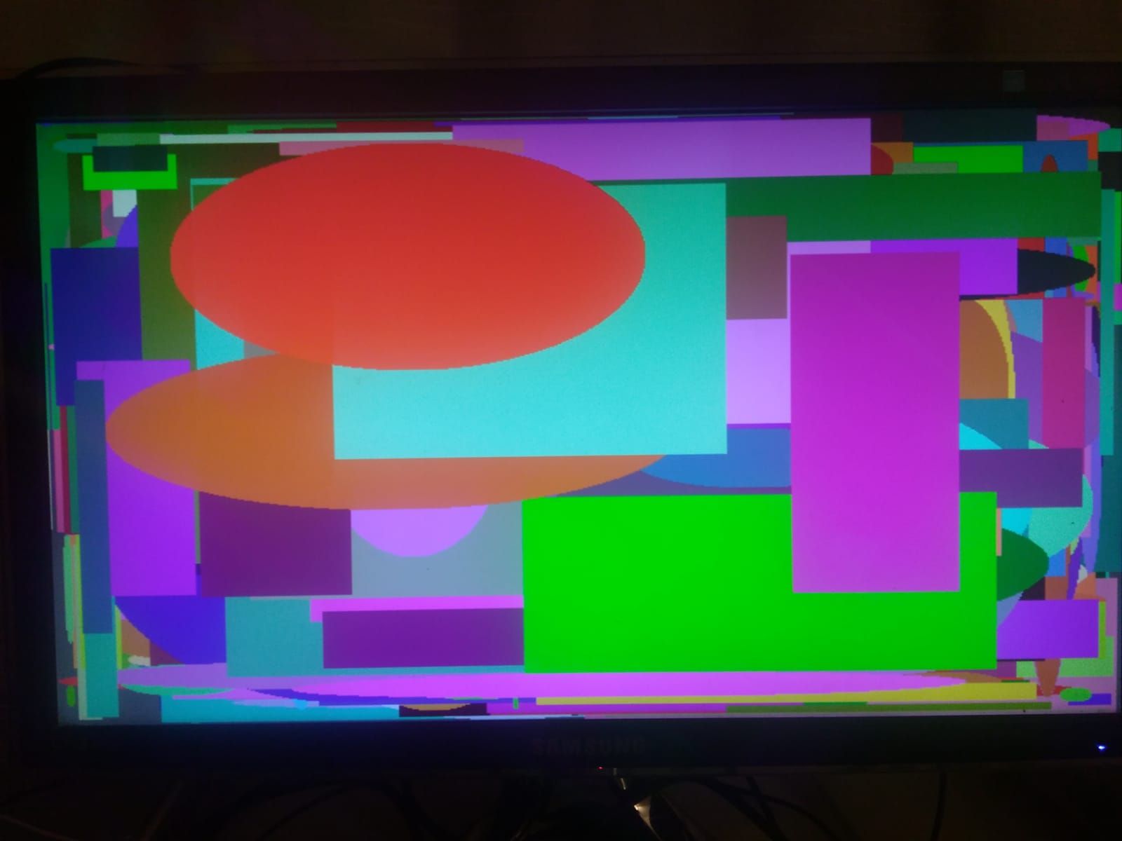
You can visually appreciate that both images seems like the same, but how we can be sure the generated Verilog behaves the same as the software implementation? The solution is to use the accelerated implementations and also call the compiled software implementation in the same SoC, then we can compare if results are the same. The test program does specifically that, reporting how many pixels are in error, if any:
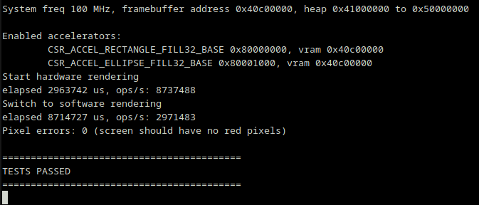
You can see that the accelerator is about 3X faster, while it also frees the CPU for other tasks.
In case of any discrepance, non-matching pixels are marked in red (this was generated by inducing a coordinate error in the software implementation) and the amount of pixels in error is reported.

Console output would be in this case:
Pixel errors: 320 (screen should have no red pixels)

==========================================
*** TESTS FAILED ***
==========================================The acceleration is readily appreciated on the following video, where the software implementation is run prior to the hardware one. After that, a clock demo application is shown, using a combination of drawn rectangles and ellipses.
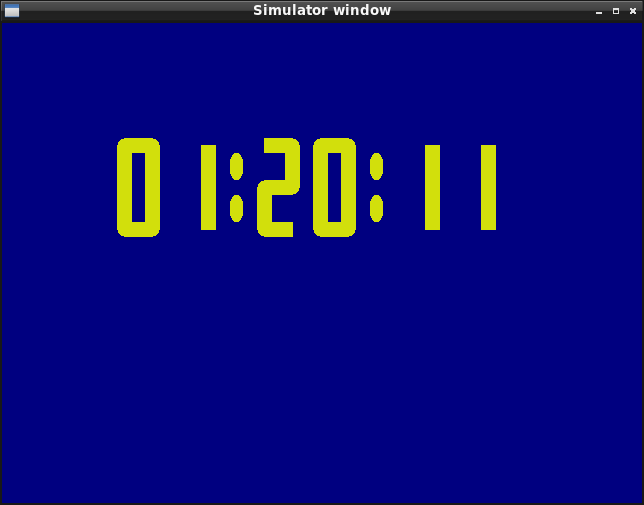
The code for that demo application can be compiled with the main simulator code on the host machine (e.g. Linux) to see results on the simulator window. This eases testing while in development since the program compiles in few seconds, then it can be run on the hardware platform to check if producing the same results. In the provided video, you can see that the hardware matches the simulator.
Accelerator cores gets directly connected to the dynamic RAM of the respective boards (acting similarly as a DMA), and using caching to achieve access at high speed. That way, the accelerated cores are about 7X faster than when running in software, as the current tests reports (line drawing core on a ECP5 device):
Start software rendering
elapsed 9057225 us, ops/s: 828153 (2 FPS @640x480)
Switch to hardware rendering
elapsed 1229585 us, ops/s: 6100246 (19 FPS @640x480)
Just waiting a bit to evaluate image...
Pixel errors: 0 (screen should have no red pixels)

==========================================
TESTS PASSED
==========================================
The following video shows the corresponding images on the display (first the software renderer, then the accelerated renderer).
Curently the project supports the following boards:
Lambdaconcept ECPIX-5 with a Lattice ECP5 device. It currently utilices an open source toolchain for building the bitstream. The board name used in the project is lambdaconcept_ecpix5.
Digilent Arty A7-35T with an AMD Artix7 device. The board name used in the project is digileny_arty.
Just run:
make BOARD=lambdaconcept_ecpix5 run uploadWhere the target run runs the simulator, and the upload target makes the bitstream and uploads it to the FPGA board.
The FPGA board is now capable of running a graphics-enabled micropython port, capable of controlling a PC monitor. Up to 8 bit per color channel are supported.
Example: accel_basic.py
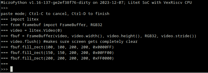
Generate and upload the bitstream (use your own serial port location if different):
make BOARD=digilent_arty digilent_arty SERIAL_PORT=/dev/ttyUSB1
cd micropython/ports/litex
make
litex_term.py --kernel build/firmware.bin /dev/ttyUSB1
cd -
openFPGALoader -b arty build/digilent_arty/gateware/digilent_arty.bit
Then the .py file can be uploaded using the standard mpremote command:
mpremote connect /dev/ttyUSB1 run demos/micropython/accel_basic.pyThis generates the following picture:
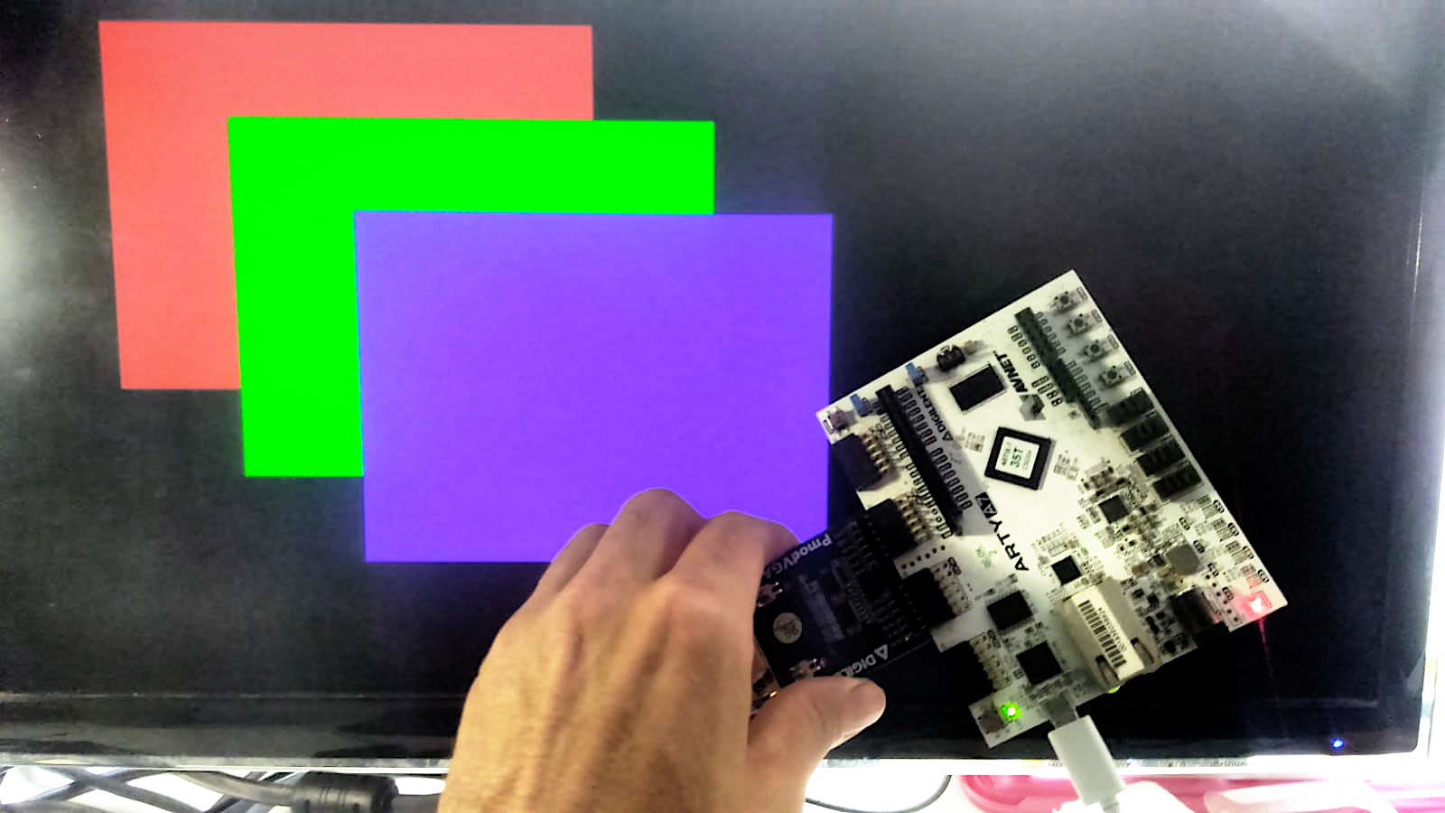
To run the clock demo, accel_clock.py (in same folder)
The same repository used for the port of micropython to the FPGA platform was used to target the project's CPU board (F133A SoC by Allwinner Tech)
Supported features are:
The repository of the extended micropython is linked as a git submodule on the main repo (see micropython@51dfc37b30 at the project's main repo). The sub repository directs to the micropython repo.
The source for the f133 port are under the following folder
A basic example to test micropython on the CPU is to use the REPL mode:
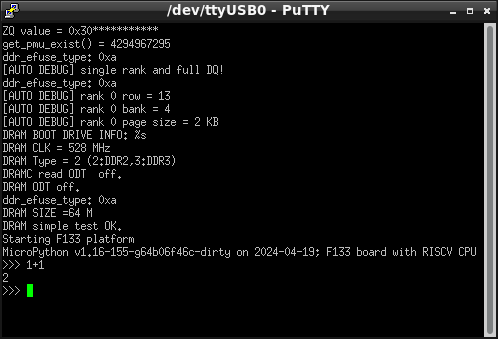
Under the f133 folder, there's a micropython script that shows how to access the video framebuffer: test/test_video.py
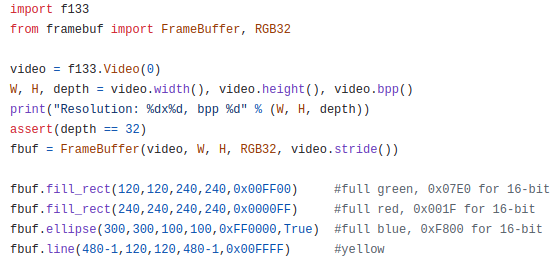
Execution of this produced the following result:
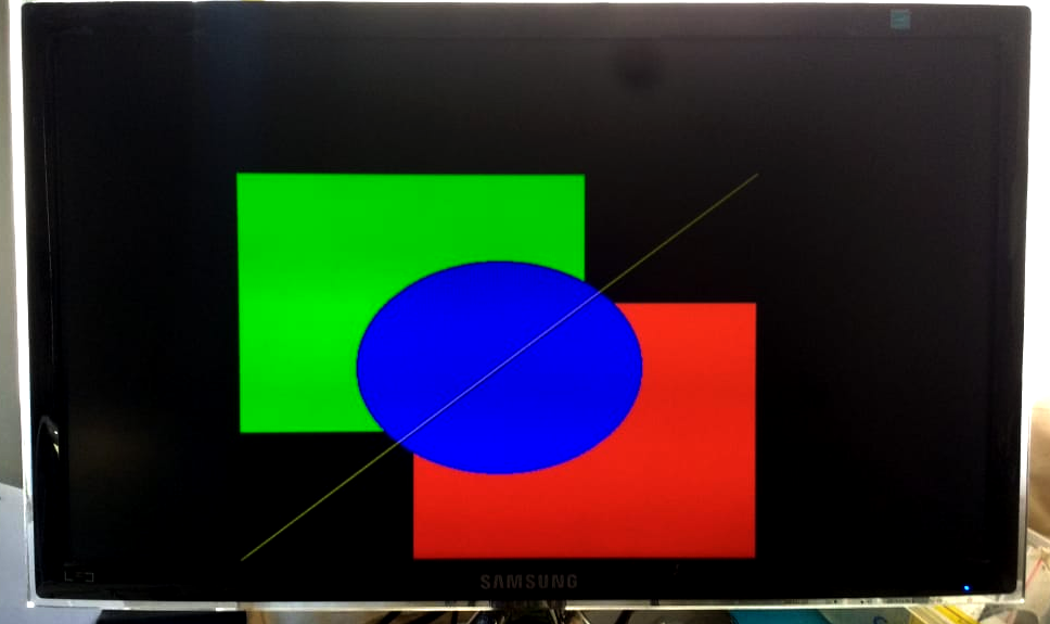
Note the compatibility of the micropython code with the one for the FPGA platform.
cd ports/f133
make
The make command will build the firmware and upload it to the board. To upload new firmware, you have to first push the reset button.
A brand-new board was designed using a graphics-capable CPU:
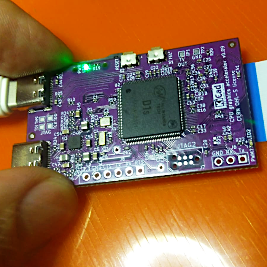
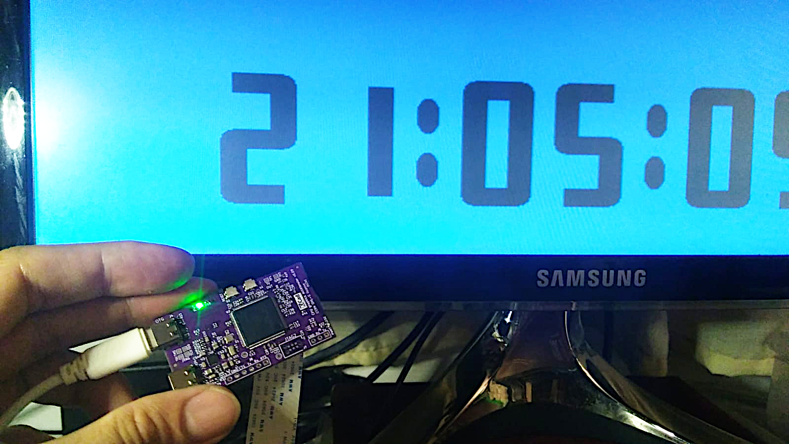
It's capable of running the clock demo, using the graphics primitives ellipse and rectangle fill
This produces the following image:
   cd target-cpu/f133-bare/
   make
The make command will build the firmware and upload it to the board. To upload new firmware, you have to first push the reset button.
This milestone is conclusive proof that this framework is capable running the drawing primitives as software or hardware, since the same code runs on the CPU as software and in the FPGA as a hardware core, producing matching visual results.
The same port of micropython to the FPGA platform was used to target the project's CPU board (F133A SoC by Allwinner Tech)
The CPU board is capable of communication using serial ports, they're typically used to control the board externally and to get debug messages.
See an example of boot mesages outputted from the default debug port (UART0):
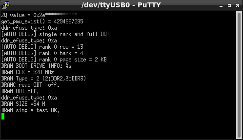
See below an example interaction with micropython using the second port (UART1), accesible in the board at the 6-pin header (bottom left).
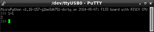
This is achieved in software by calling a initialization function uart_probe(UART_COMM) to enable the second port. See main.c for a example usage and driver_uart.c for the implementation.
An I2C driver was added to the micropython port for the CPU board. It can access display information provided by PC monitors and determine available resolutions.
It works by configuring I/O pins for open-drain behaviour, thus electrically compatible with the I2C standard. See mphalport.h for implementation details.
The micropython script to run is: i2c_vga_ddc.py, which obtains the following information:
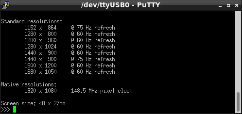
The script can be run from the Linux console with the mpremote command:
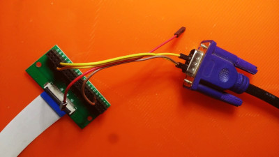
mpremote connect /dev/ttyUSB0 run demos/micropython/i2c_vga_ddc.pyThe wiring can be done using the I/O board using a 40-pin FPC cable and direct wiring to the VGA connector as shown:
A new function to decompress JPEG file was implemented, it's based on the C model of a Verilog decompressor, so in that form it's useful to test things in sofware before moving it to hardware. The original code was changed to avoid dynamic memory allocations thus easier to run in the bare metal environment, see target-cpu/f133-bare for sources.
A JPEG file is embedded in the firmware image by means of a direct include of the raw file data (.incbin directive in the rawdata.S assembler source)
The example image size is 33.8KB when compressed and 921.6 KB when decompressed (27:1 ratio). Software decompresion takes 195ms (5FPS) expected to reach 30FPS with the planned video decoder accelerator (Verilog).
Working example on the bare metal enviroment:
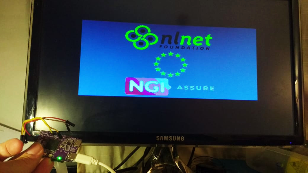
The decompression algorithm is in the c_model_jpeg_test.cpp source.

This project is funded through the NGI0 Entrust Fund, a fund established by NLnet with financial support from the European Commission's Next Generation Internet programme, under the aegis of DG Communications Networks, Content and Technology under grant agreement No 101069594.
| Qty | Value | Footprint | References |
|---|---|---|---|
| 58 | 100nF | Capacitor_SMD:C_0201_0603Metric | C15, C15, C16, C16, C20, C20, C26, C26, C30, C30, C31, C31, C32, C32, C33, C33 +42 |
| 48 | 10nF | Capacitor_SMD:C_0201_0603Metric | C1, C1, C2, C2, C14, C14, C19, C19, C25, C25, C27, C27, C38, C38, C40, C40 +32 |
| 16 | SMD_TP | Library:TestPoint_Pad_D0.5mm | TP19, TP19, TP20, TP20, TP28, TP28, TP29, TP29, TP30, TP30, TP31, TP31, TP32, TP32, TP33, TP33 |
| 14 | 4.7K | Resistor_SMD:R_0201_0603Metric | R4, R4, R21, R21, R22, R22, R23, R23, R24, R24, R26, R26, R27, R27 |
| 12 | 1uF | Capacitor_SMD:C_0402_1005Metric | C21, C21, C22, C22, C34, C34, C35, C35, C36, C36, C37, C37 |
| 12 | 50R | Resistor_SMD:R_Array_Convex_4x0402 | RN1, RN1, RN2, RN2, RN3, RN3, RN4, RN4, RN5, RN5, RN6, RN6 |
| 10 | 10uF | Capacitor_SMD:C_0402_1005Metric | C7, C7, C8, C8, C11, C11, C17, C17, C18, C18 |
| 8 | 100k | Resistor_SMD:R_0201_0603Metric | R1, R1, R13, R13, R14, R14, R25, R25 |
| 8 | 12K | Resistor_SMD:R_0201_0603Metric | R9, R9, R10, R10, R11, R11, R12, R12 |
| 8 | 2.2uH | Library:Murata_DFE201612P-2R2M=P2 | L1, L1, L2, L2, L3, L3, L4, L4 |
| 8 | SMD_TP | TestPoint:TestPoint_Pad_D1.0mm | TP1, TP1, TP2, TP2, TP26, TP26, TP27, TP27 |
| 6 | 100k 1% | Resistor_SMD:R_0201_0603Metric | R5, R5, R17, R17, R18, R18 |
| 6 | 4.7uF | Capacitor_SMD:C_0402_1005Metric | C12, C12, C46, C46, C47, C47 |
| 6 | 600R | Inductor_SMD:L_0402_1005Metric | FB1, FB1, FB2, FB2, FB3, FB3 |
| 4 | 22 | Resistor_SMD:R_0402_1005Metric | R31, R31, R32, R32 |
| 4 | 22uF | Capacitor_SMD:C_0603_1608Metric | C23, C23, C24, C24 |
| 4 | 51K | Resistor_SMD:R_0201_0603Metric | R7, R7, R8, R8 |
| 4 | Conn_02x15_Odd_Even | Library:DF12NB3030DP05V51 | J7, J7, J8, J8 |
| 4 | LOGO | LOGO | G***, G***, G***, G*** |
| 4 | USB_C_Receptacle_USB2.0 | Connector_USB:USB_C_Receptacle_G-Switch_GT-USB-7010ASV | USBD1, USBD1, USBH1, USBH1 |
| 4 | VAL** | Library:mouse-bite-2mm-slot-single | mouse-bite-2mm-slot, mouse-bite-2mm-slot, mouse-bite-2mm-slot, mouse-bite-2mm-slot |
| 2 | 0.22uF | Capacitor_SMD:C_0201_0603Metric | C10, C10 |
| 2 | 0R | Resistor_SMD:R_0402_1005Metric | R6, R6 |
| 2 | 0R | Resistor_SMD:R_0201_0603Metric | R3, R3 |
| 2 | 1.5K | Resistor_SMD:R_0201_0603Metric | R20, R20 |
| 2 | 100pF | Capacitor_SMD:C_0201_0603Metric | C13, C13 |
| 2 | 10K | Resistor_SMD:R_Array_Convex_4x0402 | RN7, RN7 |
| 2 | 10K | Resistor_SMD:R_0201_0603Metric | R28, R28 |
| 2 | 10uF | Capacitor_SMD:C_0603_1608Metric | C3, C3 |
| 2 | 120K 1% | Resistor_SMD:R_0402_1005Metric | R15, R15 |
| 2 | 15k | Resistor_SMD:R_0201_0603Metric | R33, R33 |
| 2 | 210K 1% | Resistor_SMD:R_0402_1005Metric | R29, R29 |
| 2 | 22K 1% | Resistor_SMD:R_0402_1005Metric | R2, R2 |
| 2 | 240R | Resistor_SMD:R_0402_1005Metric | R19, R19 |
| 2 | 4.7k | Resistor_SMD:R_0201_0603Metric | R34, R34 |
| 2 | 4.7uF | Capacitor_SMD:C_0603_1608Metric | C71, C71 |
| 2 | 82K 1% | Resistor_SMD:R_0402_1005Metric | R16, R16 |
| 2 | 84.5K 1% | Resistor_SMD:R_0201_0603Metric | R30, R30 |
| 2 | Conn_01x03 | Connector_PinHeader_2.54mm:PinHeader_1x03_P2.54mm_Vertical | J5, J5 |
| 2 | Conn_01x04 | Connector_PinHeader_2.54mm:PinHeader_1x04_P2.54mm_Vertical | J10, J10 |
| 2 | Conn_01x04_Male | Connector_PinHeader_2.54mm:PinHeader_1x04_P2.54mm_Vertical | J4, J4 |
| 2 | Conn_01x6_Male | Connector_PinHeader_2.54mm:PinHeader_1x06_P2.54mm_Vertical | J2, J2 |
| 2 | D_Schottky | Library:U-DFN1608-2_L1.6-W0.8-RD | D2, D2 |
| 2 | ECP5 | bosonFrameGrabber:csBGA_132 | U3, U3 |
| 2 | JTAG | Connector:Tag-Connect_TC2030-IDC-NL_2x03_P1.27mm_Vertical | J6, J6 |
| 2 | LED_ARGB | gkl_led:0404LED_RGB | D1, D1 |
| 2 | MT41K64M16TW-107_J-TR | Package_BGA:BGA-96_9.0x13.0mm_Layout2x3x16_P0.8mm | U4, U4 |
| 2 | OT252048MJBA4SL | gkl_time:Oscilator_2.5x2.0 | OSC1, OSC1 |
| 2 | RY1303 or EA3036 | Package_DFN_QFN:QFN-20-1EP_3x3mm_P0.4mm_EP1.65x1.65mm | U1, U1 |
| 2 | SW_Push | Button_Switch_SMD:SW_SPST_PTS810 | SW1, SW1 |
| 2 | SolderJumper_3_Bridged12 | Jumper:SolderJumper-3_P1.3mm_Bridged12_RoundedPad1.0x1.5mm | JP1, JP1 |
| 2 | TF TF-018 1.5mm | Library:TF-SMD_TF-018 | J9, J9 |
| 2 | TLV62569APDRL | Package_TO_SOT_SMD:SOT-563 | U2, U2 |
| 2 | TPS51206 | gkl_housings_dfn:WSON-10-1EP_2x2mm_P0.4mm | U8, U8 |
| 2 | VAL** | Library:mouse-bite-2mm-slot | mouse-bite-2mm-slot, mouse-bite-2mm-slot |
| 2 | W25Q128JVPIQ | Package_SON:WSON-8-1EP_6x5mm_P1.27mm_EP3.4x4.3mm | U6, U6 |
It measures 70 × 53.6 mm and has 6 copper layers, 1.6 mm thick.
318 parts, built around the LFE5U-85F-8MG285I, TLV62569APDRL, W25Q128JVPIQ and TF-018. The full list of its parts is on this page, with links to each part's symbol and footprint where PCBKit's library has them.
From the openconcepts-ar/accel2d repository on GitHub, at the commit this page was made from: the board is hardware/Panelized/Panelized-6layer.kicad_pcb and its schematic hardware/CPU_board/CPU_board.kicad_sch. PCBKit opens the board in the browser, with nothing to install.
Its repository states no licence, so its author keeps all rights: ask openconcepts-ar before reusing the design.
openconcepts-ar/accel2d
This project aims to provide a graphics server system based on hardware accelerated graphics, and a easy way to develop the graphics primitives.

openconcepts-ar/accel2d
This project aims to provide a graphics server system based on hardware accelerated graphics, and a easy way to develop the graphics primitives.

openconcepts-ar/accel2d
This project aims to provide a graphics server system based on hardware accelerated graphics, and a easy way to develop the graphics primitives.

openconcepts-ar/accel2d
This project aims to provide a graphics server system based on hardware accelerated graphics, and a easy way to develop the graphics primitives.

openconcepts-ar/accel2d
This project aims to provide a graphics server system based on hardware accelerated graphics, and a easy way to develop the graphics primitives.

openconcepts-ar/accel2d
This project aims to provide a graphics server system based on hardware accelerated graphics, and a easy way to develop the graphics primitives.

openconcepts-ar/accel2d
This project aims to provide a graphics server system based on hardware accelerated graphics, and a easy way to develop the graphics primitives.

openconcepts-ar/accel2d
This project aims to provide a graphics server system based on hardware accelerated graphics, and a easy way to develop the graphics primitives.

openconcepts-ar/accel2d
This project aims to provide a graphics server system based on hardware accelerated graphics, and a easy way to develop the graphics primitives.

openconcepts-ar/accel2d
This project aims to provide a graphics server system based on hardware accelerated graphics, and a easy way to develop the graphics primitives.

openconcepts-ar/accel2d
This project aims to provide a graphics server system based on hardware accelerated graphics, and a easy way to develop the graphics primitives.

openconcepts-ar/accel2d
This project aims to provide a graphics server system based on hardware accelerated graphics, and a easy way to develop the graphics primitives.


o7-machinehum/flipper-blackhat
Linux based WiFi pentesting device for the Flipper Zero.


CU-Rocketry/flight_computer
Competition Flight Computer Module 25-26

apantelic/ohmsprint_kicad
Energy measurement system designed in KiCad, including schematic, BOM, and 2-layer PCB layout