4 layers49.8 × 67.3 mm

 open-thngs/trap-a-rep-trigger1
Device to detect passing creatures to trigger an external device like a DSLR camera
Rep trap pcb is an open-source printed circuit board by open-thngs, from the open-thngs/trap-a-rep-trigger repository on GitHub. It is a 4-layer board of 154.2 × 30.1 mm with 91 parts on 91 nets, routed with 662 tracks and 202 vias.
It is built around the ESP32-S3-WROOM-1-N8, VL53L4CDV0DH/1 and AP2112K-3.3, with the DRV5032FBLPG, LESD5D5.0CT1G and SKRKAEE020 among its other parts. Its parts include 26 resistors, 19 capacitors, 8 ICs, 7 diodes and 6 connectors. It belongs with the ESP32 boards of this library.


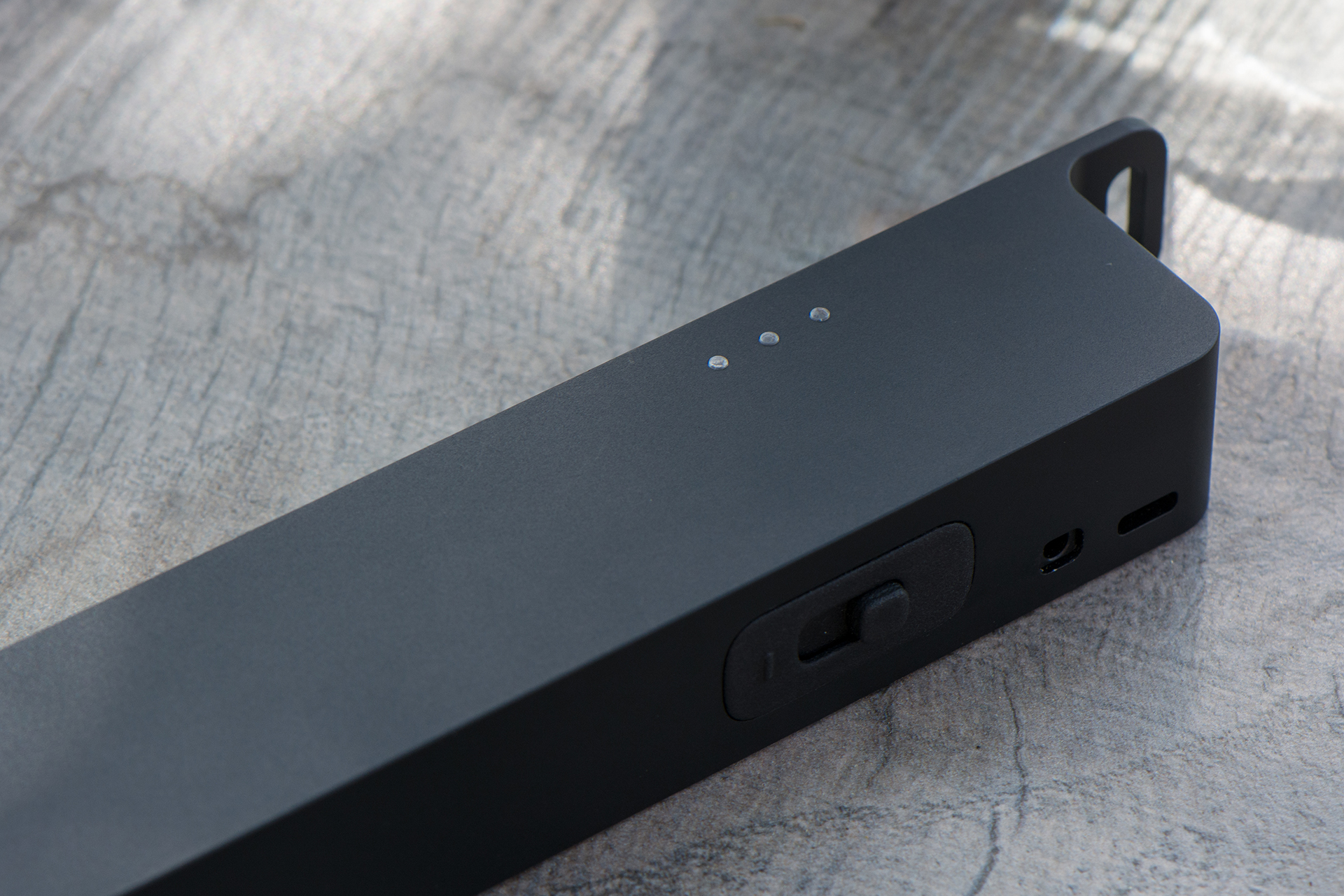
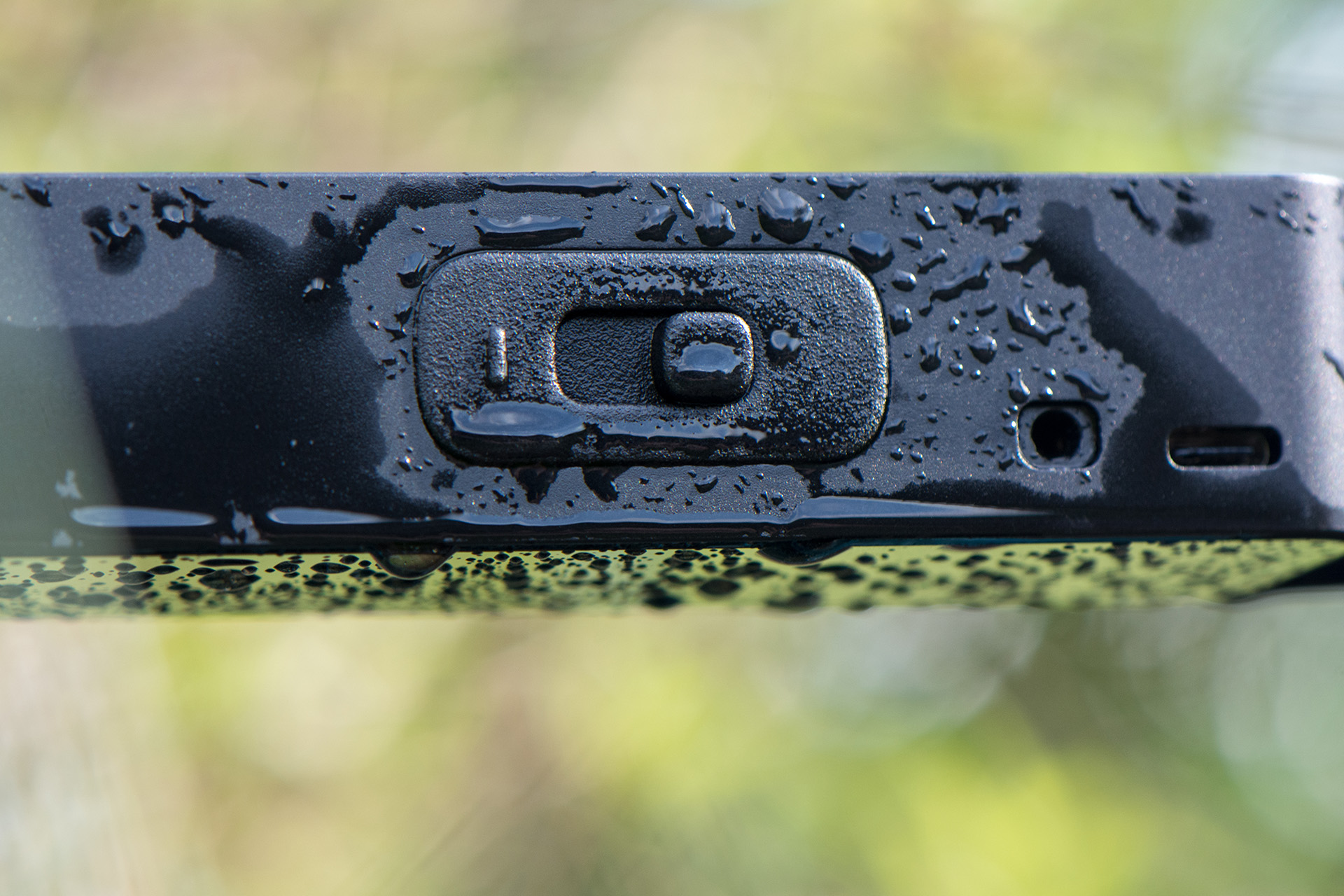
The RepTrap is a "motion detector" and camera trigger designed to detect small and/or cold-blooded animals such as frogs, lizards, birds, and other wildlife. It doesn't detect motion directly but instead identifies changes in height within the range of its four Time-of-Flight (ToF) sensors. Any height change within this range triggers a connected camera's shutter.
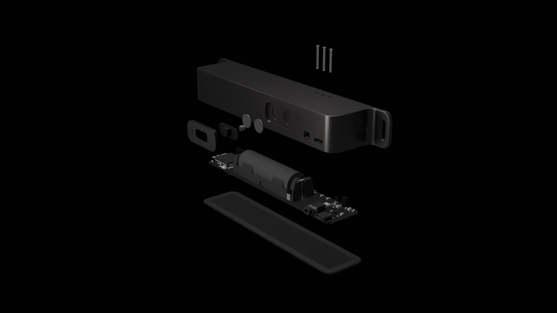
The device and software is Bluetooth ready but it is currently missing an App. Here are commands which can be send to configure and change the device:
0x7017]
0x701C]
Description: Refelcts the current device status as a string
Values: running calibrating0x7018]
Description: Accepts specific device commands
Values:
stop: Stops the BLE Service on the devicecalibrate: Triggers a re-calibration of the devicextalk: Triggers an cross-talk and offset calibration of the device (only needed for manufacturing, should not be used)trigger: Triggers the camera shutter and focus signal701D]
Description: Using this characteristic you can configure the device (experimental). You can send a 3 Byte payload consisting of the type (first byte) and tzhe data(second and third byte). Example [0xA0, 0x00, 0x00] Type 0xA0 Signal Threashold with value 0
Values:
0xA0 - Signal Threshold0xA1 - Sigma Threshold0xA2 - Time to Measure0xA3 - Measure IntervalNote: The config characteristic is experimental. The limits of the values might not be checked or some value combination might lead to an unresponsive sensor. A re-flash of the firmware might be needed to fix the device. You can read the datasheet of the ToF Sensor to get the details of this values.
Note: If you want to power the device permanently via USB-C the BLE Service will be started once you boot the device with USB-C connected. You can send teh command to stop the BLE Service to save energy.


| Qty | Value | Footprint | References |
|---|---|---|---|
| 10 | 10k | Resistor_SMD:R_0603_1608Metric | R3, R7, R8, R9, R10, R11, R12, R13, R14, R17 |
| 7 | 0.1µF | Capacitor_SMD:C_0603_1608Metric | C7, C8, C11, C12, C13, C15, C20 |
| 4 | 4.7µF | Capacitor_SMD:C_0603_1608Metric | C5, C6, C9, C10 |
| 4 | VL53L4CDV0DH/1 | VL53L4CD:LGA12_STM | U3, U4, U5, U6 |
| 3 | 10µF | Capacitor_SMD:C_0603_1608Metric | C3, C4, C14 |
| 3 | 1µF | Capacitor_SMD:C_0603_1608Metric | C1, C2, C16 |
| 3 | 2.2k | Resistor_SMD:R_0603_1608Metric | R20, R21, R29 |
| 3 | LESD5D5.0CT1G | LESD5D5.0CT1G:LESD5D50CT1G | D1, D4, D6 |
| 2 | 0.1µF/DNP | Capacitor_SMD:C_0603_1608Metric | C17, C18 |
| 2 | 0R | Resistor_SMD:R_0603_1608Metric | R15, R16 |
| 2 | 1k | Resistor_SMD:R_0603_1608Metric | R5, R6 |
| 2 | 47R | Resistor_SMD:R_0603_1608Metric | R23, R24 |
| 2 | 5k1 | Resistor_SMD:R_0603_1608Metric | R1, R22 |
| 2 | MountingHole_Pad | MountingHole:MountingHole_2.5mm_Pad_Via | H1, H2 |
| 2 | SKRKAEE020 | SKRKAEE020:SKRKAEE020 | SW1, SW2 |
| 2 | TP_3V3 | TestPoint:TestPoint_Pad_D1.0mm | TP3, TP17 |
| 1 | 10k/DNP | Resistor_SMD:R_0603_1608Metric | R19 |
| 1 | 124018612112A | 124018612112A:CONN_124018612112A_AMP | J8 |
| 1 | 1k2 | Resistor_SMD:R_0603_1608Metric | R25 |
| 1 | 2k | Resistor_SMD:R_0603_1608Metric | R4 |
| 1 | 390R | Resistor_SMD:R_0603_1608Metric | R30 |
| 1 | 4.7k | Resistor_SMD:R_0603_1608Metric | R2 |
| 1 | AP2112K-3.3 | Package_TO_SOT_SMD:SOT-23-5 | U1 |
| 1 | APHF1608LSEEQBDZGKC | APHF1608LSEEQBDZGKC:APHF1608LSEEQBDZGKC | LED2 |
| 1 | BH-18650-B1BA002 | 1042P:1042P | BT1 |
| 1 | Conn_01x02_Pin | Connector_PinSocket_2.54mm:PinSocket_1x02_P2.54mm_Vertical | J5 |
| 1 | DNP | Connector_PinSocket_2.54mm:PinSocket_1x06_P2.54mm_Vertical | J9 |
| 1 | DRV5032FBLPG | DRV5032DULPGM:DRV5032DULPGM | IC1 |
| 1 | ESP32-S3-WROOM-1 | ESP32-S3:ESP32-S3-WROOM-1 | U7 |
| 1 | GND | TestPoint:TestPoint_Pad_2.0x2.0mm | J7 |
| 1 | ILD213T | Package_SO:SO-8_3.9x4.9mm_P1.27mm | D5 |
| 1 | Jumper_2_Bridged | Jumper:SolderJumper-2_P1.3mm_Bridged_RoundedPad1.0x1.5mm | JP2 |
| 1 | LED_GREEN | LED_SMD:LED_0603_1608Metric | D3 |
| 1 | LED_RED | LED_SMD:LED_0603_1608Metric | D2 |
| 1 | LOGO | LOGO | G1 |
| 1 | MCP73831/OT | Package_TO_SOT_SMD:SOT-23-5 | U2 |
| 1 | PJ-3254A-SMT | SJ-3541AS-SMT-TR-67:CUI_SJ-3541AS-SMT-TR-67 | J3 |
| 1 | SolderJumper_2_Open | Jumper:SolderJumper-2_P1.3mm_Open_TrianglePad1.0x1.5mm | JP1 |
| 1 | TB_SDA | TestPoint:TestPoint_Pad_D1.0mm | TP1 |
| 1 | TP_EN_ESP | TestPoint:TestPoint_Pad_D1.0mm | TP12 |
| 1 | TP_FOCUS | TestPoint:TestPoint_Pad_D1.0mm | TP16 |
| 1 | TP_GPIO0 | TestPoint:TestPoint_Pad_D1.0mm | TP13 |
| 1 | TP_INT_1 | TestPoint:TestPoint_Pad_D1.0mm | TP5 |
| 1 | TP_INT_2 | TestPoint:TestPoint_Pad_D1.0mm | TP7 |
| 1 | TP_INT_3 | TestPoint:TestPoint_Pad_D1.0mm | TP11 |
| 1 | TP_INT_4 | TestPoint:TestPoint_Pad_D1.0mm | TP9 |
| 1 | TP_LDO_EN | TestPoint:TestPoint_Pad_D1.0mm | TP14 |
| 1 | TP_SCL | TestPoint:TestPoint_Pad_D1.0mm | TP2 |
| 1 | TP_SHUTTER | TestPoint:TestPoint_Pad_D1.0mm | TP15 |
| 1 | TP_XSHUT_1 | TestPoint:TestPoint_Pad_D1.0mm | TP4 |
| 1 | TP_XSHUT_2 | TestPoint:TestPoint_Pad_D1.0mm | TP6 |
| 1 | TP_XSHUT_3 | TestPoint:TestPoint_Pad_D1.0mm | TP10 |
| 1 | TP_XSHUT_4 | TestPoint:TestPoint_Pad_D1.0mm | TP8 |
| 1 | VBUS | TestPoint:TestPoint_Pad_2.0x2.0mm | J4 |
It measures 154.2 × 30.1 mm and has 4 copper layers, 1.6 mm thick.
91 parts, built around the ESP32-S3-WROOM-1-N8, VL53L4CDV0DH/1, AP2112K-3.3 and DRV5032FBLPG. The full list of its parts is on this page, with links to each part's symbol and footprint where PCBKit's library has them.
From the open-thngs/trap-a-rep-trigger repository on GitHub, at the commit this page was made from: the board is pcb/rep-trap-pcb.kicad_pcb and its schematic pcb/main.kicad_sch. PCBKit opens the board in the browser, with nothing to install.
Its repository states no licence, so its author keeps all rights: ask open-thngs before reusing the design.

pa3gsb/Radioberry-2.x-extensions
Hardware extensions to the Radioberry Ham Radio


rapha-tech/ESP32-hema-console
New PCB for the small console from hema to use an ESP32


awesomebrownies/cyberdeck
Deck Featuring: Controllers, shock cage, folding travel mode, and picatinny rails


oddgrd/auge
This repo contains the kicad PCB files, as well as libraries for footprints and symbols, for my [VL53L4CD][https://www.st.com/en/imaging-and-photonics-solutions/vl53l4cd.html] daughterboard.