4 layers43 × 95 mm
Oe commutator controller
open-ephys/commutator-controller
Open Ephys commutator PCB and firmware
107 parts2

 open-ephys/commutators5
Active coaxial commutator for electrophysiology
Oe commutator controller is an open-source printed circuit board by open-ephys, from the open-ephys/commutators repository on GitHub. It is a 4-layer board of 43 × 95 mm with 92 parts on 88 nets, routed with 752 tracks and 391 vias.
It is built around the RP2040, TMC2130-LA and W25Q128JVSIQ, with the AP2112K-3.3, PTN04050CAZ and ABM8AIG-12.000MHZ-12-2Z-T3 among its other parts. Its parts include 37 capacitors, 24 resistors, 8 ICs, 5 switches and 3 connectors. It belongs with the RP2040 boards of this library.


[!Important]
This repository has been split into dedicated repositories for each design:
- https://github.com/open-ephys/commutator-coax
- https://github.com/open-ephys/commutator-spi
- https://github.com/open-ephys/commutator-dual
- etc.
Future commutator designs, issue tracking, etc. will take place in those repositories. This repository is deprecated.
The wide-spread availability of 6 degree of freedom pose tracking using internal-measurement units (IMUs) allows continuous monitoring of an animal's rotational state in an environment. This obviates the need for tether torque measurements to drive an active commutator since the rotational state of the animal is known in real-time, and the commutator can simply follow along. This permits the use of extremely thin coaxial tethers that cannot function with a standard active commutator because they are too flexible to translate rotational torque.
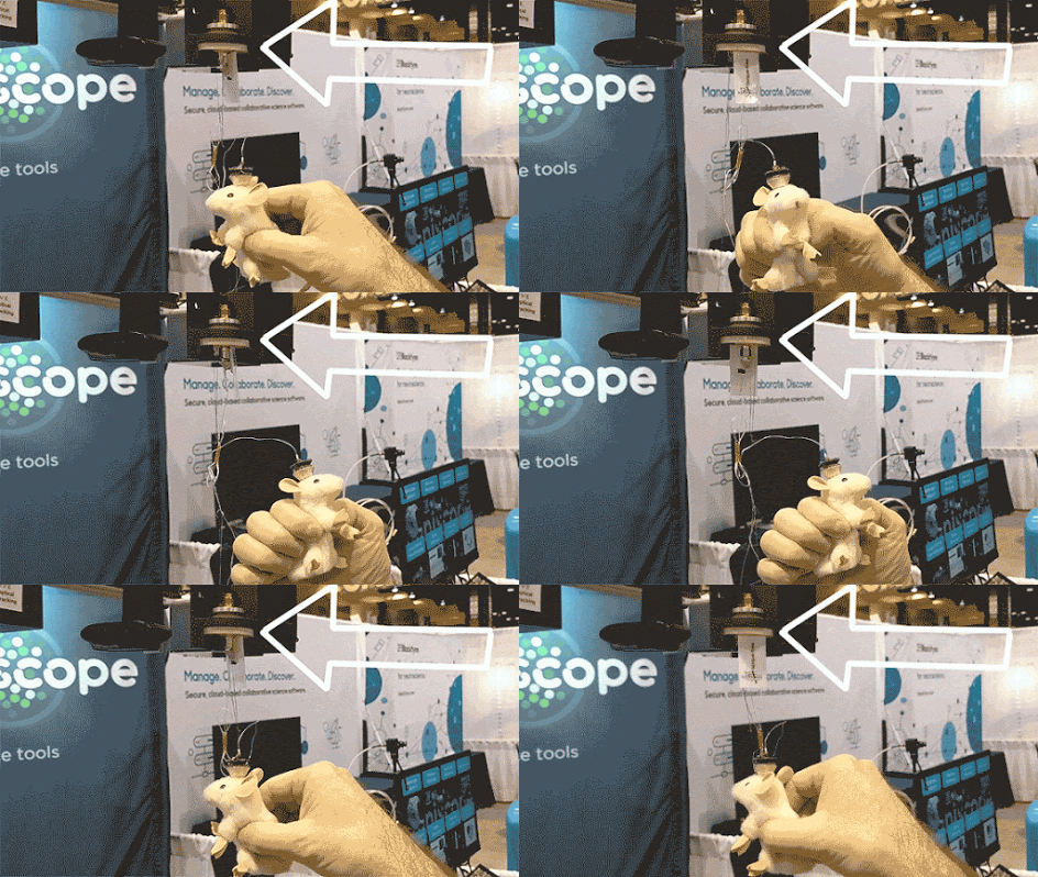
This commutator functions with headstages and miniscopes that provide provide appropriate rotational tracking information. Currently supported devices are next-generation, serialized headstages and miniscopes such as ONIX headstages, and UCLA Miniscope 4.0, and Open Ephys 3D low-profile SPI headstages. However, this device operations completely independently from the headstage itself, so can be used with any device that provides accurate, drift-free rotational state. It can even be used without an IMU, e.g. using video-based rotation tracking since its remote control interface is agnostic to how rotational measurements are taken.
Note: A high-quality, within-spec micro USB cable must be used when connecting the commutator to the host computer.
The LED tells you about the commutator state:
The front panel has four buttons.
Enable/Disable: toggle commutator enable/disable.
Directional (2x): Manually control the motor rotation in the direction indicated on each button when the commutator is Enabled. These inputs take precedence over and override ongoing remote motor control. When pressed, all target turns provided via remote control will be cleared, such that releasing them will not result in the commutator re-engaging an old target position. Remote commands sent when a button is being pressed are ignored.
LED: pressing the LED will toggled on and off (e.g for cases where it presents an unwanted visual stimulus).
When manual buttons are not being pressed, the commutator accepts JSON-encoded commands over its serial interface. Here are examples of all commands that can be sent:
{enable : true}     // Enable commutator (default = false)
{led : false}       // Turn off RGB LED (default = true)
{speed : 250}       // Set turn speed to 250 RPM (default = 50 RPM, valid ∈ (0, 500] RPM)
{turn : 1.1}        // 1.1 turns CW
{turn : -1.1}       // 1.1 turns CCW

// Example multi-command. Any combo can be used.
// In this case:
// 1. Turn LED off
// 1. Set speed to 25 RPM
// 2. Excecute 1.1 turns CC
// Ordering of commands does not matter, it is determined by the firmware
{led: false, speed: 25, turn : -1.1}
The communator state can be read using the {print:} command which will
return a JSON object containing version, state, and motor parameters.
All control and speed parameters, whether changed via the remote or manual interface, are saved in non-volatile memory each time they are changed. The device will start in the same state it was last used.
The controller firmware is located here. It runs on a Teensy lc. To compile this firmware and program the microcontroller, you need the following dependencies:
The firmware can be uploaded to the device using the Arduino
IDE. Note that you will need to add
the Teensyduino add-on to to
the Arduino IDE to program the Teensy. When installing Teensyduino, you should
opt to install all of the bundled libraries as well. This takes care of
installing AccelStepper library rather than having to install it manually.
ArduinoJSON can be installed through the Arduino IDE's package manager.
The BOM is located here.
The mechanical component of the commutator are as follows:
Mechanical designs are located here. STL files for 3D printing
are located in the stl subdirectory. Links to purchase each of these
components, including 3D-printed parts, can be found on the BOM.
The board used to control the commutator consists of the following elements:
Board designs and manufacturing files are located here.
This license pertains to documents in the control-board, mechanical, and
resources subdirectory.
This work is licensed to Jonathan P. Newman and Jakob Voigts under CC BY-NC-SA 4.0. To view a copy of this license, visit https://creativecommons.org/licenses/by-nc-sa/4.0
The creation of commercial products using the hardware documentation in this repository is not permitted without an explicit, supplementary agreement between the Licensor and the Licensee. Please get in touch if you are interested in commercially distributing this tool.
This license pertains to documents in the source code in the firmware
subdirectory.
Copyright Jonathan P. Newman
Permission is hereby granted, free of charge, to any person obtaining a copy of this software and associated documentation files (the "Software"), to deal in the Software without restriction, including without limitation the rights to use, copy, modify, merge, publish, distribute, sublicense, and/or sell copies of the Software, and to permit persons to whom the Software is furnished to do so, subject to the following conditions:
The above copyright notice and this permission notice shall be included in all copies or substantial portions of the Software.
THE SOFTWARE IS PROVIDED "AS IS", WITHOUT WARRANTY OF ANY KIND, EXPRESS OR IMPLIED, INCLUDING BUT NOT LIMITED TO THE WARRANTIES OF MERCHANTABILITY, FITNESS FOR A PARTICULAR PURPOSE AND NONINFRINGEMENT. IN NO EVENT SHALL THE AUTHORS OR COPYRIGHT HOLDERS BE LIABLE FOR ANY CLAIM, DAMAGES OR OTHER LIABILITY, WHETHER IN AN ACTION OF CONTRACT, TORT OR OTHERWISE, ARISING FROM, OUT OF OR IN CONNECTION WITH THE SOFTWARE OR THE USE OR OTHER DEALINGS IN THE SOFTWARE.
| Qty | Value | Footprint | References |
|---|---|---|---|
| 12 | 0.1uF | Capacitor_SMD:C_0402_1005Metric | C2, C3, C4, C5, C6, C7, C8, C9, C10, C11, C13, C19 |
| 6 | 0.1uF | Capacitor_SMD:C_0603_1608Metric | C18, C27, C28, C31, C32, C36 |
| 5 | 4.7uF | Capacitor_SMD:C_0805_2012Metric | C25, C30, C33, C35, C37 |
| 4 | 1uF | Capacitor_SMD:C_0603_1608Metric | C1, C12, C38, C39 |
| 4 | 4.7k | Resistor_SMD:R_0603_1608Metric | R1, R2, R23, R24 |
| 4 | LOGO | LOGO | G***, G***, G***, G*** |
| 4 | ~ | oe:Touch_Center_2mm | S1, S2, S3, S4 |
| 4 | ~ | MountingHole:MountingHole_2.7mm_M2.5_ISO7380 | H1, H2, H3, H4 |
| 4 | ~ | TestPoint:TestPoint_Pad_D2.0mm | TP1, TP2, TP3, TP4 |
| 3 | 10k | Resistor_SMD:R_0603_1608Metric | R14, R17, R18 |
| 2 | 0.11,0.5W | Resistor_SMD:R_1206_3216Metric | R20, R21 |
| 2 | 100uF | Capacitor_SMD:C_Elec_8x10.2 | C21, C24 |
| 2 | 10k | Resistor_SMD:R_0402_1005Metric | R3, R5 |
| 2 | 22pF | Capacitor_SMD:C_0402_1005Metric | C14, C15 |
| 2 | 22uF | Capacitor_SMD:C_1206_3216Metric | C22, C23 |
| 2 | 27 | Resistor_SMD:R_0402_1005Metric | R4, R6 |
| 2 | 5.1k | Resistor_SMD:R_0402_1005Metric | R8, R9 |
| 2 | HV0820-2R7305-R | Capacitor_SMD:C_1210_3225Metric | C20, C26 |
| 1 | 0.47uF | Capacitor_SMD:C_0805_2012Metric | C29 |
| 1 | 0015910100 | Connector_PinHeader_2.54mm:PinHeader_2x05_P2.54mm_Vertical_SMD | J1 |
| 1 | 1.2M | Resistor_SMD:R_0603_1608Metric | R13 |
| 1 | 1.33k | Resistor_SMD:R_0603_1608Metric | R12 |
| 1 | 1.5M | Resistor_SMD:R_0603_1608Metric | R10 |
| 1 | 160k | Resistor_SMD:R_0603_1608Metric | R11 |
| 1 | 1719730004 | oe:MOLEX_1719730004_1x04_P2.54mm_Vert_Lock | J3 |
| 1 | 1K | Resistor_SMD:R_0402_1005Metric | R7 |
| 1 | 2.2 | Resistor_SMD:R_0603_1608Metric | R19 |
| 1 | 2.49k | Resistor_SMD:R_0603_1608Metric | R16 |
| 1 | 22nF | Capacitor_SMD:C_0603_1608Metric | C34 |
| 1 | 30k | Resistor_SMD:R_0603_1608Metric | R22 |
| 1 | 51k | Resistor_SMD:R_0603_1608Metric | R15 |
| 1 | ABM8AIG-12.000MHZ-12-2Z-T3 | Crystal:Crystal_SMD_Abracon_ABM8AIG-4Pin_3.2x2.5mm | Y1 |
| 1 | AP2112K-3.3 | Package_TO_SOT_SMD:SOT-23-5 | U9 |
| 1 | CAP1296-x-AIA | Package_DFN_QFN:DFN-10-1EP_3x3mm_P0.5mm_EP1.55x2.48mm | U4 |
| 1 | IS31FL3193 | Package_DFN_QFN:DFN-10-1EP_3x3mm_P0.5mm_EP1.65x2.38mm | U8 |
| 1 | LTC4425 | Package_SO:MSOP-12-1EP_3x4mm_P0.65mm_EP1.65x2.85mm | U6 |
| 1 | PTN04050CAZ | oe:TI_R-PDSS_B4_SMD | U5 |
| 1 | RP2040 | Package_DFN_QFN:QFN-56-1EP_7x7mm_P0.4mm_EP3.2x3.2mm | U2 |
| 1 | SW_MEC_5E | oe:PANASONIC_EVQP7-JA-01P | SW1 |
| 1 | TMC2130-LA | Package_DFN_QFN:QFN-36-1EP_5x6mm_P0.5mm_EP3.6x4.1mm | U7 |
| 1 | TSM-102-01-L-SV | Connector_PinHeader_2.54mm:PinHeader_1x02_P2.54mm_Vertical_SMD_Pin1Left | JP1 |
| 1 | USB4110-GF-A | Connector_USB:USB_C_Receptacle_GCT_USB4110 | J2 |
| 1 | W25Q128JVS | Package_SO:SOIC-8_5.23x5.23mm_P1.27mm | U1 |
| 1 | XZMDKCBDDG45S-9 | oe:SUNLED_PLCC4-INV_3.2x2.8x1.9mm | D1 |
It measures 43 × 95 mm and has 4 copper layers, 1.6 mm thick.
92 parts, built around the RP2040, TMC2130-LA, W25Q128JVSIQ and AP2112K-3.3. The full list of its parts is on this page, with links to each part's symbol and footprint where PCBKit's library has them.
From the open-ephys/commutators repository on GitHub, at the commit this page was made from: the board is pcb/oe-commutator-controller.kicad_pcb and its schematic pcb/cap-charger.kicad_sch. PCBKit opens the board in the browser, with nothing to install.
Its repository states no licence, so its author keeps all rights: ask open-ephys before reusing the design.
open-ephys/commutator-controller
Open Ephys commutator PCB and firmware

RocketryVT/active-drag-system
Eigen Library, cmake, and arm-none-eabi-gcc tooling required for successful build.


mathieupommery/ESE_2526_ROBOTCHATDELAMUERTE
We first wanted to make a three omniwheeled robot with FOC control on brushless motors.


open-ephys/ephys-test-board
General purpose, automated electrophysiology test board


golioth/ostentus-hw
A PCB front panel for Golioth's Aludel hardware platform