4 layers50.8 × 36.8 mm
 onomondo/getting-started7
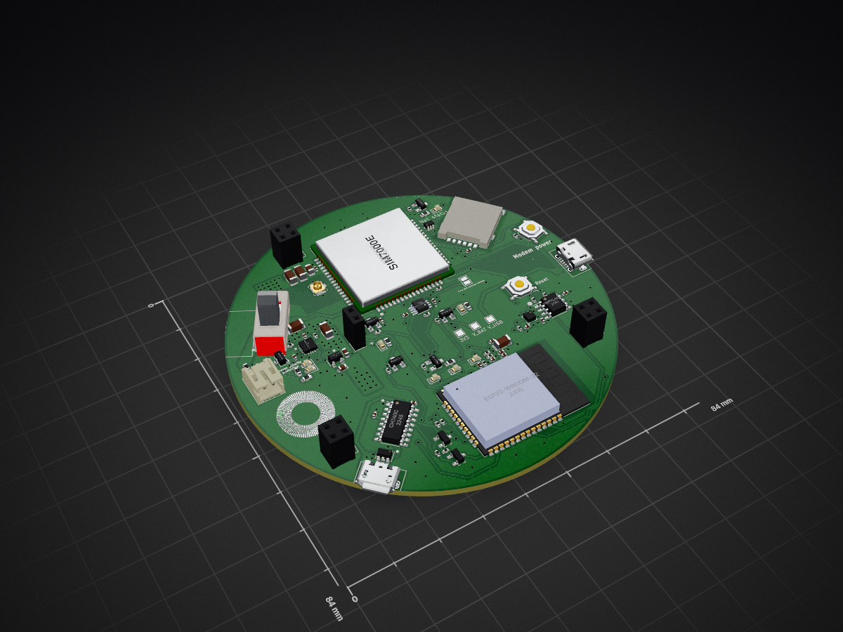
Onomondo Getting Started development kit. Board design files and firmware.
Sim7070 is an open-source printed circuit board by onomondo, from the onomondo/getting-started repository on GitHub. It is a 4-layer board with 96 parts on 136 nets, routed with 764 tracks and 249 vias.
It is built around the CH340C, ESP32-WROOM-32 and SIM7000E, with the TMP75AIDR(UMW), BQ24074RGTR and KXTJ3-1057 among its other parts. Its parts include 27 resistors, 25 capacitors, 9 ICs, 9 diodes and 9 connectors. It belongs with the ESP32 boards of this library.


Example forked from esp-idf repo.
The kit is designed to showcase some of the features provided by Onomondo. Already a customer? Head over to app.onomondo.com/getting-started to get a guided tour of the platform and to see the data packets in real-time.

Specifically, this example is powered by the Onomondo Connectors. It removes complexity (i.e. Cloud SDK) from the device and let the network handle it. Check out the code snippet below - would you have guessed that this is fully encrypted and integrated into the Azure IoT Hub? Get more info on Connectors here.
//init cellular connectivity
esp_err_t status = initCellular(SIM7xxx, 0);
...
...
// setup of sensor
...
...
// open a socket to a non-existing server
status = openSocket("1.2.3.4", 4321);

// payload formatting
sprintf(payload, "{\"battery\": %f,\"signal\": %f,\"temperature\": %f}", battery, signal, temp);

// transmit payload
status = sendData(payload, strlen(payload), 0);
This it what happens on the platform:
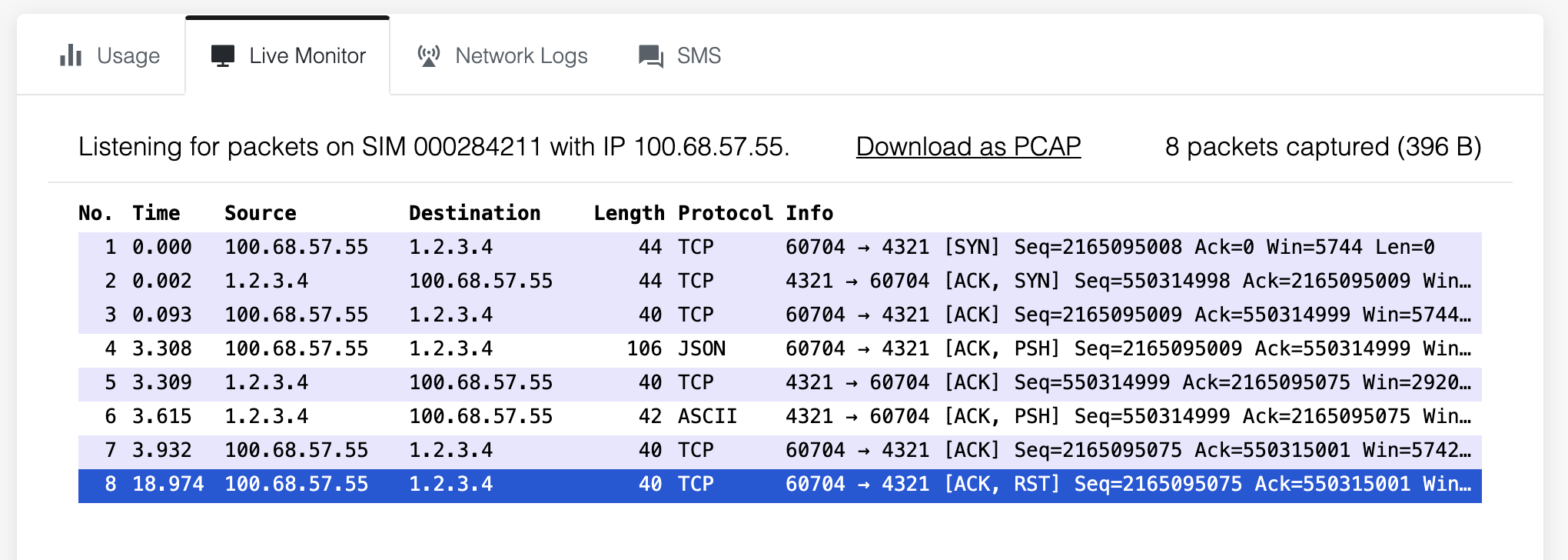
At this point the data has not yet reached any public networks. Since the SIM has a Connector configured, the payload gets neatly wrapped up and securely handed over to Azure IoT Hub (but not limited to Azure: Want a webhook event: ✔, any major cloud provider ✔, custom TLS endpoint ✔).
This is from the Azure Logs:

Notice how the network has added a few fields: A timestamp and a sim_id so the device can be identified. In addition to the extra fields everything has been fully encrypted.
The kit is fully programmed when you get it. However, you are encouraged to modify the example we have provided.
First time use: Flick the power switch and the device should come online. The device will search for networks, register on a network and establish a data connection. Touch the touch-pad on the front to transmit a message with the current temperature, battery voltage and last known signal level. After a while the device will enter a low power state. Give it a shake to wake it up again.
On app.onomondo.com/getting-started you'll get the full tour.
In case the stock firmware gets overwritten, you can easily flash the device with a precompiled binary. Download the ESP flash download tool here, download the precompiled firmware (onomondo_getting_started.bin) from the repo and flash the device.
These procompiled binaries will in the future include firmware to assist in debugging connectivity with Onomondo.
Run idf.py --ccache -p PORT build flash monitor to build and flash the project..
(To exit the serial monitor, type Ctrl-].)
See the ESP-IDF Getting Started Guide for full steps to configure and use ESP-IDF to build projects.
If the device fails to connect (red flashing LED).
Check the Network logs on the Onomondo platform. Does the platform report any activity?
Plug the device into you computer (use the port marked as MCU Debug on the back). Have a look at the out below and see if anything stands out. Does the modem reponds to any commands? When does it stop responding?
I (451) main: Cpu freq: 160 MhZ
I (451) ACC: Config i2c param
I (461) ACC: Install i2c driver
I (461) ACC: Reading register....
I (481) main: Temperature: 26.500000
I (481) gpio: GPIO[4]| InputEn: 0| OutputEn: 1| OpenDrain: 0| Pullup: 0| Pulldown: 0| Intr:0
I (481) gpio: GPIO[5]| InputEn: 0| OutputEn: 1| OpenDrain: 0| Pullup: 0| Pulldown: 0| Intr:0
I (491) gpio: GPIO[25]| InputEn: 0| OutputEn: 1| OpenDrain: 0| Pullup: 0| Pulldown: 0| Intr:0
I (511) touch_driver: test init: touch pad [6] val is 686
I (511) uart: queue free spaces: 30
I (511) sim800: PWR pin 27
I (511) gpio: GPIO[27]| InputEn: 0| OutputEn: 1| OpenDrain: 0| Pullup: 0| Pulldown: 0| Intr:0
I (521) AT CMD: AT
E (621) esp-modem: esp_modem_dte_send_cmd(352): process command timeout
E (621) dce_service: esp_modem_dce_power_test(251): send command failed
I (721) AT CMD: AT
I (721) AT RESP: AT

E (721) esp-modem: esp_dte_handle_line(136): handle line failed
E (721) esp-modem: AT

I (721) AT RESP: OK

I (721) sim800: Modem is on!| Qty | Value | Footprint | References |
|---|---|---|---|
| 17 | 100n | Capacitor_SMD:C_0402_1005Metric | C3, C5, C6, C12, C13, C14, C15, C16, C17, C18, C19, C20, C21, C23, C24, C30 +1 |
| 14 | 10k | Resistor_SMD:R_0402_1005Metric | R1, R2, R6, R9, R11, R15, R16, R20, R21, R22, R23, R26, R27, R28 |
| 6 | 500 | Resistor_SMD:R_0603_1608Metric | R3, R10, R13, R17, R18, R25 |
| 5 | NDS355N | footprints:SSOT-3 | Q1, Q4, Q5, Q6, Q7 |
| 4 | WHITE | LED_SMD:LED_0603_1608Metric | D1, D8, D9, D11 |
| 3 | 1M | Resistor_SMD:R_0402_1005Metric | R5, R8, R12 |
| 3 | 4u7 | Capacitor_SMD:C_1206_3216Metric | C8, C11, C22 |
| 3 | Conn_02x02_Odd_Even | GettingStarted:PinSocket_2x02_P2.54mm_Vertical_centered | J6, J8, J9 |
| 3 | GREEN | LED_SMD:LED_0603_1608Metric | D2, D3, D5 |
| 3 | TestPoint_Small | TestPoint:TestPoint_Pad_1.5x1.5mm | TP2, TP3, TP4 |
| 2 | 100u | Capacitor_SMD:C_1206_3216Metric | C9, C10 |
| 2 | 10u | Capacitor_SMD:C_0603_1608Metric | C1, C2 |
| 2 | 4k7 | Resistor_SMD:R_0402_1005Metric | R14, R19 |
| 2 | MMSS8050-H-TP | digikey-footprints:SOT-23-3 | Q2, Q8 |
| 2 | SMD-BUTTON_4P-5.2X5.2X1.5MM-SKQGADE010_ | OPL_Switch:SW4-SMD-5.2X5.2X1.5MM | SW1, SW2 |
| 2 | USB_B_Micro | GettingStarted:USB_Micro_B_JLC | J5, J7 |
| 1 | 1u | Capacitor_SMD:C_0805_2012Metric | C4 |
| 1 | 2k | Resistor_SMD:R_0402_1005Metric | R7 |
| 1 | 3k1 | Resistor_SMD:R_0402_1005Metric | R4 |
| 1 | BQ24074RGTR | SnapEDA Library:QFN50P300X300X100-17N | U9 |
| 1 | CH340C | Package_SO:SOIC-16_3.9x9.9mm_P1.27mm | U5 |
| 1 | Conn_02x01 | Connector_PinSocket_2.54mm:PinSocket_1x02_P2.54mm_Vertical | J10 |
| 1 | DIP-JST-2P-2.0 | Connector_JST:JST_PH_S2B-PH-K_1x02_P2.00mm_Horizontal | J4 |
| 1 | ESDA6V1-5SC6 | Package_TO_SOT_SMD:SOT-23-6 | D7 |
| 1 | ESP32-WROOM-32 | SnapEDA Library:MODULE_ESP32-WROOM-32 | U6 |
| 1 | Fuse | Fuse:Fuse_0603_1608Metric | F1 |
| 1 | KXTJ3-1057 | GettingStarted:KIONIX_KXTJ3-1057 | U8 |
| 1 | LOGO | logo:logo_front_logo | G*** |
| 1 | MSQA6V1W5T2G | footprints:On_Semiconductor-MSQA6V1W5T2G-Manufacturer_Recommended | U3 |
| 1 | Q_PMOS_SDG | GettingStarted:SOT-23-MOSFET | Q3 |
| 1 | RED | LED_SMD:LED_0603_1608Metric | D6 |
| 1 | SIM7000E | footprints:SIMCON_SIM7000E | U2 |
| 1 | SIM8051-6-0-14-01-X-REVD | GettingStarted:SNO-1305-B_NANO_SIM | J2 |
| 1 | SW_DPDT_x2 | GettingStarted:SWITCH_3A | SW3 |
| 1 | TMP75AIDR | Package_SO:SOIC-8_3.9x4.9mm_P1.27mm | U4 |
| 1 | TXS0102DCTR | SnapEDA Library:SOP65P400X130-8N | U7 |
| 1 | TestPoint_2Pole | Jumper:SolderJumper-2_P1.3mm_Open_Pad1.0x1.5mm | TP1 |
| 1 | U_FL-R-SMT-1_10_ | digikey-footprints:Coax_Conn_U.FL | J1 |
| 1 | XC6220B331MR | Package_TO_SOT_SMD:SOT-23-5 | U1 |
96 parts, built around the CH340C, ESP32-WROOM-32, SIM7000E and TMP75AIDR(UMW). The full list of its parts is on this page, with links to each part's symbol and footprint where PCBKit's library has them.
From the onomondo/getting-started repository on GitHub, at the commit this page was made from: the board is hardware/sim7070/sim7070.kicad_pcb. PCBKit opens the board in the browser, with nothing to install.
Its repository states no licence, so its author keeps all rights: ask onomondo before reusing the design.


tscircuit/dataset-srj24
Ten production-oriented KiCad boards converted to Simple Route JSON


epremeaux/AVTokyo_2022_Badge
AVTokyo 2022 event badge PCB, firmware and server code.

albertdolata/Sensitive-Parameter-Recorder
This repository is intended for an academic project.
