2 layers59.7 × 31.1 mm
Electricity meter zigbee
ondras12345/electricity-meter
An STM32-based datalogger for electricity meters with pulse LED
36 partsMIT

 ondras12345/electricity-meter
An STM32-based datalogger for electricity meters with pulse LED
Electricity meter is an open-source printed circuit board by ondras12345, from the ondras12345/electricity-meter repository on GitHub, published under the MIT licence. It is a 2-layer board of 90.2 × 61 mm with 95 parts on 83 nets, routed with 516 tracks and 20 vias.
It is built around the MAX3485EESA, DS3231MZ+ and 1N4148W, with the ESD5Z5V0, 0ZCJ0016FF2E and BSS138 among its other parts. Its parts include 28 resistors, 16 diodes, 15 capacitors, 9 connectors and 6 ICs. It belongs with the sensors and measurement boards of this library.


An STM32-based datalogger for electricity meters with pulse LED.
This repository contains both the PCB design files and firmware source code.
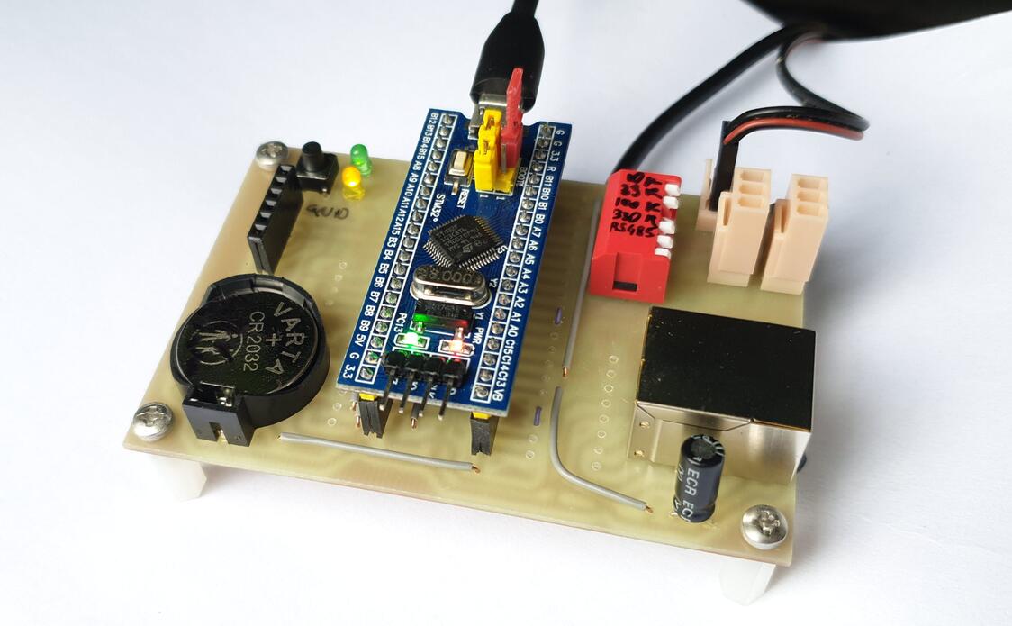
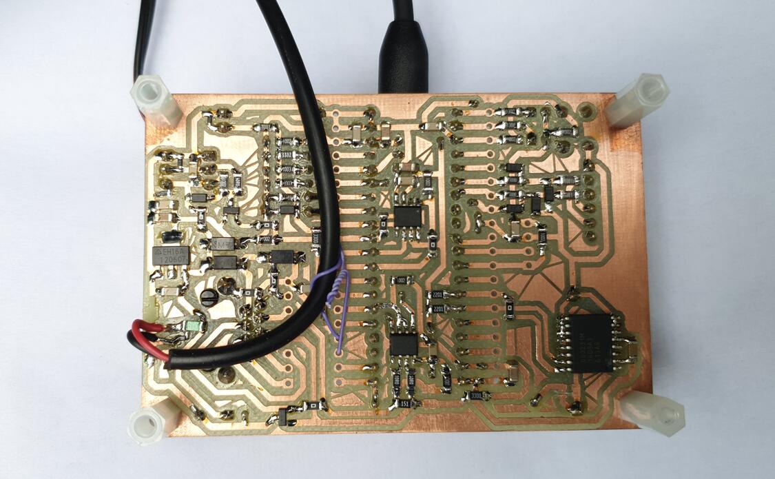
I milled the single sided PCB on my CNC machine.
Some notes:
make help  # show available commands
make  # build
make check  # run cppcheck
For uploading to the STM32 via STlink, I use tools/mkbin and
tools/upload_latest.
| Qty | Value | Footprint | References |
|---|---|---|---|
| 8 | 100n | Capacitor_SMD:C_1206_3216Metric_Pad1.33x1.80mm_HandSolder | C2, C4, C5, C8, C10, C12, C14, C15 |
| 8 | 10k | Resistor_SMD:R_1206_3216Metric_Pad1.30x1.75mm_HandSolder | R10, R12, R15, R16, R17, R20, R26, R27 |
| 7 | NetTie_2 | Resistor_SMD:R_1206_3216Metric_Pad1.30x1.75mm_HandSolder | NT1, NT2, NT3, NT4, NT5, NT6, NT7 |
| 6 | 1N4148W | Diode_SMD:D_SOD-123 | D2, D3, D4, D5, D6, D14 |
| 5 | 330 | Resistor_SMD:R_1206_3216Metric_Pad1.30x1.75mm_HandSolder | R11, R18, R19, R24, R25 |
| 4 | 10u | Capacitor_SMD:C_1206_3216Metric_Pad1.33x1.80mm_HandSolder | C6, C7, C11, C13 |
| 4 | MountingHole | MountingHole:MountingHole_3.2mm_M3 | H1, H2, H3, H4 |
| 4 | SolderJumper_2_Bridged | Jumper:SolderJumper-2_P1.3mm_Bridged_Pad1.0x1.5mm | JP1, JP2, JP4, JP5 |
| 3 | 10 | Resistor_SMD:R_1206_3216Metric_Pad1.30x1.75mm_HandSolder | R21, R22, R28 |
| 3 | 1N4007 | Diode_SMD:D_SMA_Handsoldering | D8, D9, D10 |
| 3 | 1k | Resistor_SMD:R_1206_3216Metric_Pad1.30x1.75mm_HandSolder | R1, R3, R4 |
| 3 | ESD5Z5V0 | Diode_SMD:D_SOD-523 | D7, D15, D16 |
| 2 | 100 | Resistor_SMD:R_1206_3216Metric_Pad1.30x1.75mm_HandSolder | R7, R8 |
| 2 | 2k2 | Resistor_SMD:R_1206_3216Metric_Pad1.30x1.75mm_HandSolder | R13, R14 |
| 2 | 330k | Resistor_SMD:R_1206_3216Metric_Pad1.30x1.75mm_HandSolder | R2, R5 |
| 2 | Conn_01x03 | Connector_Molex:Molex_KK-254_AE-6410-03A_1x03_P2.54mm_Vertical | J8, J9 |
| 2 | Conn_01x20_Pin | Connector_PinHeader_2.54mm:PinHeader_1x20_P2.54mm_Vertical | J1, J4 |
| 1 | 0ZCJ0016FF2E | Fuse:Fuse_1206_3216Metric_Pad1.42x1.75mm_HandSolder | F1 |
| 1 | 100k | Resistor_SMD:R_1206_3216Metric_Pad1.30x1.75mm_HandSolder | R6 |
| 1 | 100u | ondra:CP_Radial_D5.0mm_P5.00mm | C3 |
| 1 | 10n | Capacitor_SMD:C_1206_3216Metric_Pad1.33x1.80mm_HandSolder | C1 |
| 1 | 150 / 0.25W | Resistor_SMD:R_1206_3216Metric_Pad1.30x1.75mm_HandSolder | R23 |
| 1 | 330n | Capacitor_SMD:C_1206_3216Metric_Pad1.33x1.80mm_HandSolder | C9 |
| 1 | 33k | Resistor_SMD:R_1206_3216Metric_Pad1.30x1.75mm_HandSolder | R9 |
| 1 | AZ1117-3.3 | Package_TO_SOT_SMD:SOT-223-3_TabPin2 | U3 |
| 1 | BSS138 | Package_TO_SOT_SMD:SOT-23 | Q1 |
| 1 | CR2032 | ondra:BatteryHolder_DS1092-04-B6P | BT1 |
| 1 | ChinaBluePill | chinabluepill:ChinaBluePill | U2 |
| 1 | Conn_01x02_Pin | Connector_Molex:Molex_KK-254_AE-6410-02A_1x02_P2.54mm_Vertical | J2 |
| 1 | Conn_01x08 | Connector_PinHeader_2.54mm:PinHeader_1x08_P2.54mm_Vertical | J6 |
| 1 | DCF-3850N-800 | Connector_Molex:Molex_KK-254_AE-6410-04A_1x04_P2.54mm_Vertical | U4 |
| 1 | DS3231M | Package_SO:SOIC-16W_7.5x10.3mm_P1.27mm | U1 |
| 1 | ESB228110100Z | ondra:USB_Micro-B_Amphenol_10104110_Horizontal_power_only | J5 |
| 1 | ESD5Z3.3T1G | Diode_SMD:D_SOD-523 | D1 |
| 1 | FTDI breakout | ondra:FTDI_breakout | J3 |
| 1 | GREEN | LED_THT:LED_D3.0mm | D12 |
| 1 | MAX3485EESA | Package_SO:SO-8_3.9x4.9mm_P1.27mm | U6 |
| 1 | MX25L3233FM1 | Package_SO:SOP-8_3.9x4.9mm_P1.27mm | U5 |
| 1 | RJ45_Shielded | Connector_RJ:RJ45_HALO_HFJ11-x2450HRL_Horizontal | J7 |
| 1 | SM712_SOT23 | Package_TO_SOT_SMD:SOT-23 | D13 |
| 1 | SW_DIP_x06 | Button_Switch_THT:SW_DIP_SPSTx06_Piano_10.8x16.8mm_W7.62mm_P2.54mm | SW1 |
| 1 | SW_Push | Button_Switch_THT:SW_PUSH_6mm | SW2 |
| 1 | SolderJumper_2_Bridged | Resistor_SMD:R_1206_3216Metric_Pad1.30x1.75mm_HandSolder | JP3 |
| 1 | YELLOW | LED_THT:LED_D3.0mm | D11 |
ondras12345/electricity-meter
An STM32-based datalogger for electricity meters with pulse LED

mengxyz/BBS_BUFFER_A
Based on the original BBS Buffer A project: https://github.com/4061N/BBS-Buffer-A


kbssrikar7/esp32-energy-meter-pcb
KiCad PCB design for an ESP32-based single-phase energy meter (ATM90E26 metering AFE) — DRC/ERC-clean, SPICE-validated, fab-ready

nikolai2111/Multilayout-ESP-Wordclock_HW
Hardware (PCB) for an ESP32-C3 based word clock with support of different layouts and languages.

bartkepl/RDE_board
Resistance DEcade with SCPI, UART, USB, RS485 and ETHERNET in 3U eurocard format


It measures 90.2 × 61 mm and has 2 copper layers, 1.6 mm thick.
95 parts, built around the MAX3485EESA, DS3231MZ+, 1N4148W and ESD5Z5V0. The full list of its parts is on this page, with links to each part's symbol and footprint where PCBKit's library has them.
From the ondras12345/electricity-meter repository on GitHub, at the commit this page was made from: the board is hardware/electricity-meter/electricity-meter.kicad_pcb and its schematic hardware/electricity-meter-zigbee/electricity-meter-zigbee.kicad_sch. PCBKit opens the board in the browser, with nothing to install.
Its repository publishes it under the MIT licence: you may reuse it on that licence's terms (keep the author's notice, and for a copyleft licence share your changes alike).