
2 layers33.7 × 97.8 mm
HAN ESP TSS721
UtilitechAS/amsreader-firmware
ESP8266 and ESP32 compatible firmware to read, interpret and publish data to MQTT from smart electrical meters, both DLMS and DSMR is supported
29 parts470
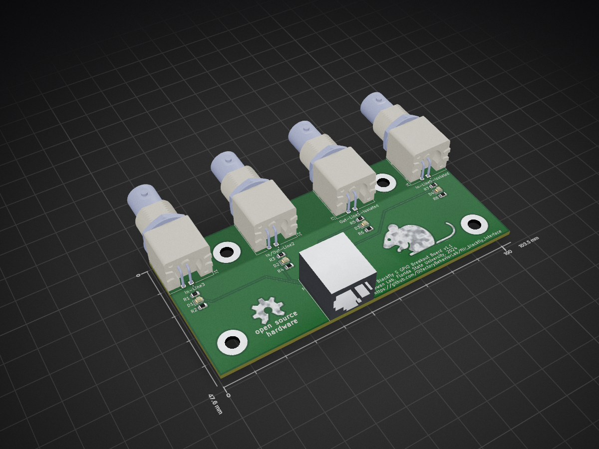
 OlfactoryBehaviorLab/flir_blackfly_interface
The Flir Blackfly S series of cameras have a GPIO interface that is exposed via a military-style DIN connector. The FSU Psychology Instrument Development shop generously attached a section of Ethernet cable to the DIN…
Flir blackfly interface is an open-source printed circuit board by OlfactoryBehaviorLab, from the OlfactoryBehaviorLab/flir_blackfly_interface repository on GitHub, published under the GPL-3.0 licence. It is a 2-layer board of 103.5 × 47.6 mm with 23 parts on 15 nets, routed with 40 tracks and 0 vias.
It is built around the RJ45. Its parts include 8 resistors, 5 connectors and 4 diodes. It belongs with the interfaces and adapters boards of this library.
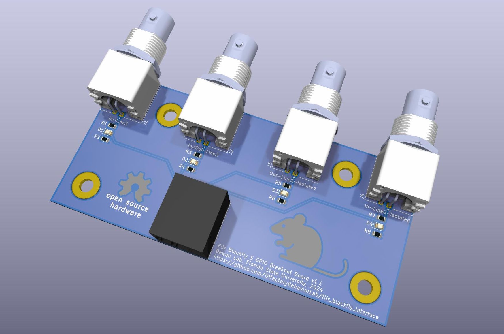
The Flir Blackfly S series of cameras have a GPIO interface that is exposed via a military-style DIN connector. The FSU Psychology Instrument Development shop generously attached a section of Ethernet cable to the DIN connector. For flexibility, we attached a RJ-45 connector to the opposite end of the cable. Our behavioral controllers expose TTL-level IO via a series of BNC connectors. To facilitate easy connection of our behavioral controller IO to the camera GPIO, we created a small RJ-45 to BNC adapter board.
The board has a very simple design that connects the RJ-45 pins to the BNC outputs. Two of the GPIO pins are opto-isolated inside the camera. These two GPIO pins and their associated BNC connectors are connected to their own ground plane that returns to the opto-isolated ground connection.
The other two GPIO pins are not opto-isolated and are connected to the power ground of the camera. These two GPIO pins and their associated BNC connectors return via a separate ground plane connected to the power ground.
The board is setup for active HIGH inputs. Each input is pulled low using 1k resistors.
Four, M4-sized mounting holes are placed on the board for convenience.
This project is licensed under GNU General Public License v3.0. You can find the included copy of the license here. For more information about the license and its terms, please visit SPDX
| Qty | Value | Footprint | References |
|---|---|---|---|
| 4 | 1k | Resistor_SMD:R_0805_2012Metric | R1, R3, R5, R7 |
| 4 | LED | LED_SMD:LED_0805_2012Metric | D1, D2, D3, D4 |
| 4 | MountingHole_Pad | MountingHole:MountingHole_4.3mm_M4_Pad | H1, H2, H3, H4 |
| 4 | R_Small_US | Resistor_SMD:R_0805_2012Metric | R2, R4, R6, R8 |
| 1 | In-Line0-Isolated | Library:LINX_CONBNC002 | J4 |
| 1 | In-Line3 | Library:LINX_CONBNC002 | J1 |
| 1 | In/Out-Line2 | Library:LINX_CONBNC002 | J2 |
| 1 | Out-Line1-Isolated | Library:LINX_CONBNC002 | J3 |
| 1 | RJ45 | Connector_RJ:RJ45_Amphenol_54602-x08_Horizontal | J5 |
| 1 | VAL** | Library:OSHW_COPPER_10MM | OSHW_COPPER_1 |
The 22 most common of 23 parts.
It measures 103.5 × 47.6 mm and has 2 copper layers, 1.6 mm thick.
23 parts, built around the RJ45. The full list of its parts is on this page, with links to each part's symbol and footprint where PCBKit's library has them.
From the OlfactoryBehaviorLab/flir_blackfly_interface repository on GitHub, at the commit this page was made from: the board is kicad_project/flir_blackfly_interface.kicad_pcb and its schematic kicad_project/flir_blackfly_interface.kicad_sch. PCBKit opens the board in the browser, with nothing to install.
Its repository publishes it under the GPL-3.0 licence: you may reuse it on that licence's terms (keep the author's notice, and for a copyleft licence share your changes alike).
UtilitechAS/amsreader-firmware
ESP8266 and ESP32 compatible firmware to read, interpret and publish data to MQTT from smart electrical meters, both DLMS and DSMR is supported

travisgoodspeed/goodfet
An embedded bus adapter for various microcontrollers and radios.


nv1t/standing-desk-interceptor
I wanted to intercept the communication between my Flexispot standing desk buttons. This is the progress on the project


Severson-Group/AMDC-Hardware
Circuit board designs for controlling advanced motor systems

mfkiwl/KiwiSDR_PCB
KiCAD PCB files for KiwiSDR project including active antenna and bias tee