2 layers60.5 × 40.1 mm
Mlab modules ISM01 ISM01
punkfab/pcb-corpus
235 real KiCad boards from open-source hardware repositories, prepared as a placement and routing benchmark
98 parts1

 oilcrest/TFSIK01
ThunderFly SiK radio ISM band UAV MAVlink telemetry link.
TFSIK01 is an open-source printed circuit board by oilcrest, from the oilcrest/TFSIK01 repository on GitHub, published under the GPL-3.0 licence. It is a 2-layer board of 50 × 30 mm with 70 parts on 56 nets, routed with 341 tracks and 237 vias.
It is built around the SI1060-A-GM, PE4259-63 and QPL9547, with the ABS07-120-32.768KHZ-T and SM06B-GHS-TB among its other parts. Its parts include 26 capacitors, 10 inductors, 9 resistors, 5 ICs and 4 connectors. It belongs with the radio and wireless boards of this library.


The TFSIK01 is a high-end open-source hardware design of a UAV modem utilizing SiK firmware. It uses the latest Si1000 series chip Si1060, which is equipped with Si4463 EZRadioPRO Transceiver. The RF front-end is designed to have high immunity to jamming using the out-of-band frequencies. This gives TFSIK special features such as being operable in the proximity of out-of-band signal jammers. RF noise immunity is a hardware-based feature; therefore, it is extremely reliable, but the proper antenna and frequency band must be used for the best results. Please contact ThunderFly s.r.o. to get support and consultation.
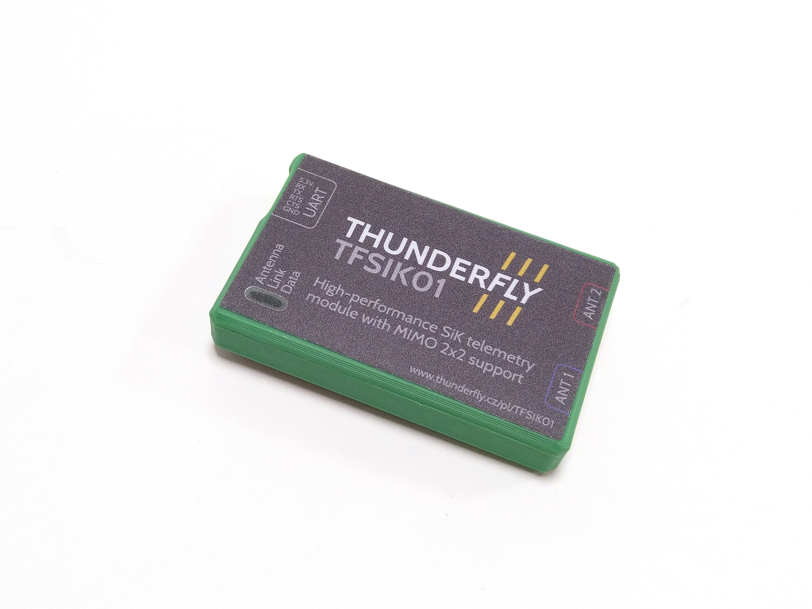
The device can be purchased directly from ThunderFly s.r.o.. Contact us by email at sale@thunderfly.cz for commercial support (Manufacturing aid, Licensing, RF verification, certification, etc.). We are the primary designers of this modem hardware and major Si1060 firmware contributors, and therefore, we can react even to non-standard requests for modification or functions (RF-band, output power, jamming resistance, etc.). The TFSIK is also available at the Tindie or Lectronz store in the most standard configurations.
The above parameters are guaranteed only in the case of the use of a proper RF antenna matched for a given frequency band. When using an improper antenna with a radio modem, several issues may arise that could affect the performance, efficiency, and reliability of the system. Here is a simplified list:
The TFSIK modem is enclosed in a 3D-printed box suitable for user modification. Inside that box are electronics with electromagnetic shielding.
Here is a photo of TFSIK electronics with the essential electromagnetic shielding cover removed.
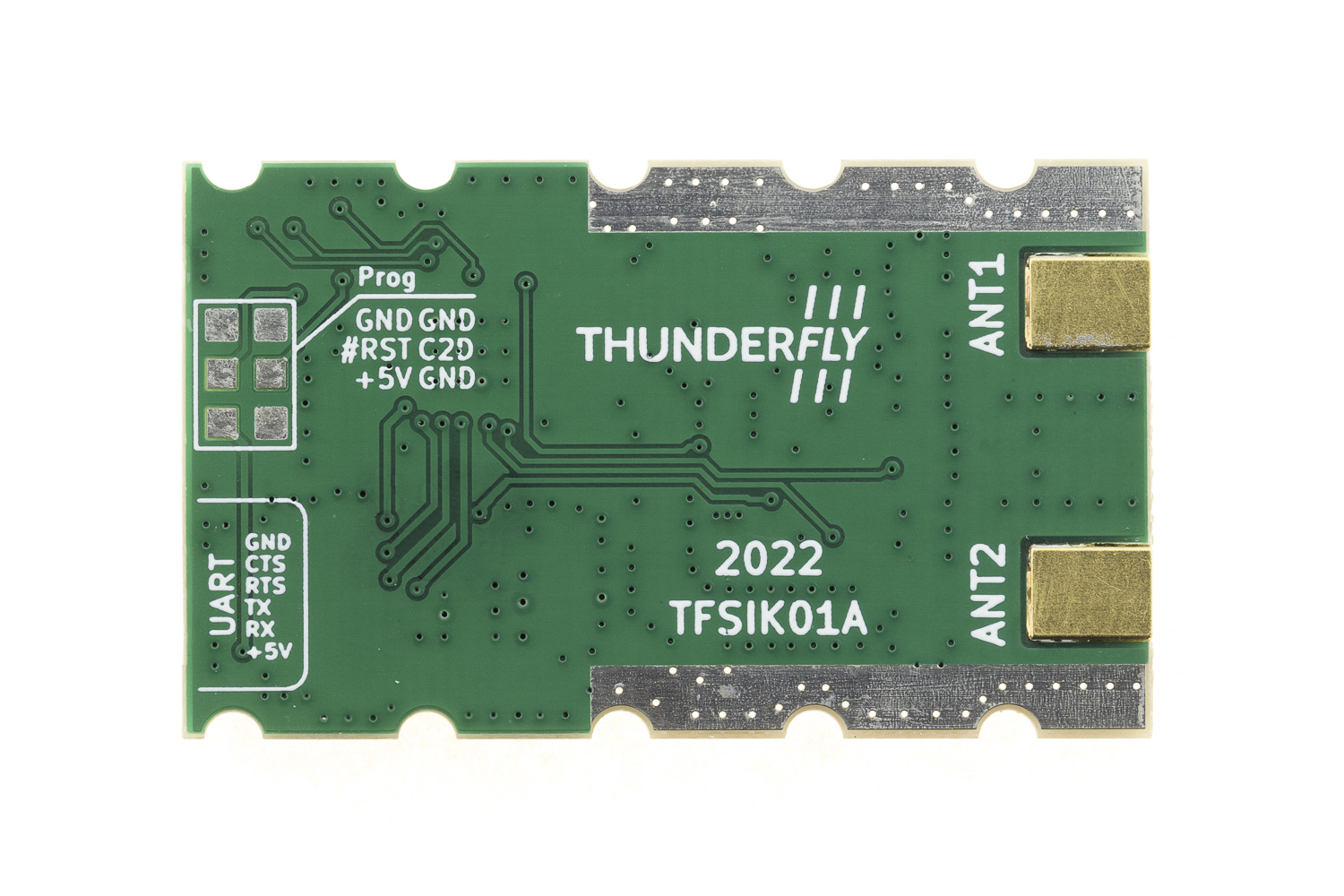
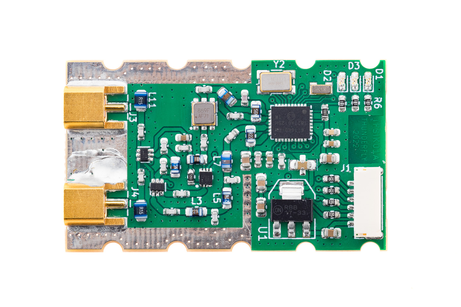
External antennas are connected to the TFSIK modem by a pair of MCX connectors. For ease of use, we prepared a kit with simple whip antennas. This kit could be manufactured for multiple frequency bands. Here is 433 MHz as an example. The antenna kit strictly pairs only with the TFSIK modem tuned on the same frequency band.
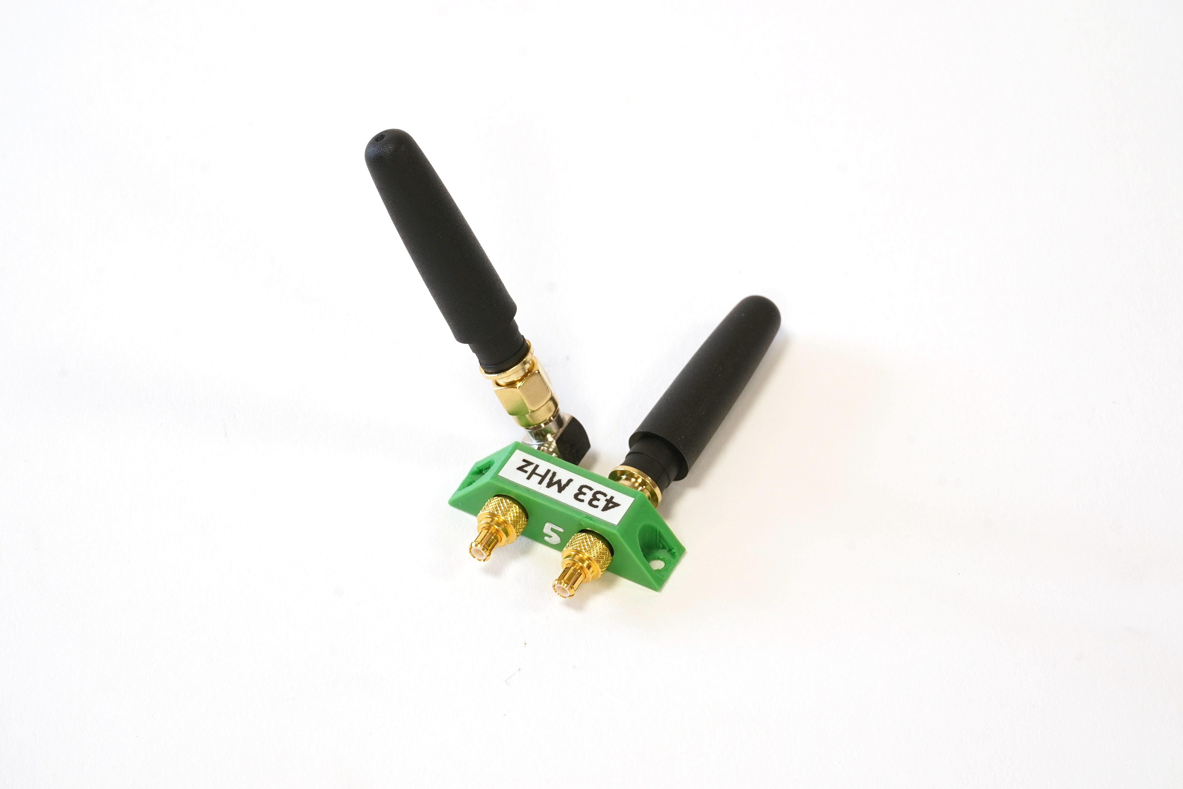
As you can see, the antenna kit contains two asymmetrically mounted antennas. The antenna is tightened in position by SMA connectors. The optimal position depends on your exact setup, but generally, the antennae should be orthogonal to each other due to their "donut" radiation patterns. The whole setup of TFSIK01 with the antenna kit should be mounted by a pair of screws in the holes of the antenna kit.
The TFSIK modem is intended to be used at the UAV as an "in the air" part of the communication link. For the ground control station, the TFMODEM is supposed to be used.
The reasons for the difference in the air and ground control station units are design tradeoffs.
For example, the ground control unit needs a very reliable interface; therefore, there is a large interface USB connector to the ground control station computer. The same connector is impractical to use in the UAV part. Similar restrictions apply to the RF filters, antenna connectors, etc. To resolve that, we decided to use different implementations of the ground station.
SiK firmware is commonly used in radio modems, particularly in the fields of unmanned aerial vehicles (UAVs) and robotics. When integrated into a Robot Operating System (ROS) or ROS2 environment, SiK technology offers several advantages. It provides reliable and long-range communication, which is crucial for both indoor and outdoor robotic applications. The low latency of TFSIK01 modems ensures real-time responsiveness, a critical factor in robotics. These modems are highly configurable, offering users the flexibility to tailor the system according to specific needs. Additionally, their compatibility with various communication protocols makes them easy to integrate into existing ROS and ROS2 systems.
More details about the TFSIK01 telemetry modem can be found on ThunderFly's documentation website.
| Qty | Value | Footprint | References |
|---|---|---|---|
| 10 | HOLE_TF | Mlab_Mechanical:dira_3mm | M1, M2, M3, M4, M5, M6, M7, M8, M9, M10 |
| 8 | 100pF | Capacitor_SMD:C_0603_1608Metric | C2, C4, C17, C26, C27, C31, C33, C34 |
| 5 | 10uF | Capacitor_SMD:C_0805_2012Metric | C1, C3, C5, C18, C20 |
| 4 | 33R | Resistor_SMD:R_0603_1608Metric | R1, R2, R3, R4 |
| 3 | 180R | Resistor_SMD:R_0603_1608Metric | R6, R22, R23 |
| 3 | 9.1pF | Capacitor_SMD:C_0603_1608Metric | C7, C28, C29 |
| 3 | ~ | Inductor_SMD:L_0805_2012Metric_Pad1.15x1.40mm_HandSolder | L8, L9, L10 |
| 2 | 100nF | Capacitor_SMD:C_0603_1608Metric | C16, C19 |
| 2 | 150nH | Inductor_SMD:L_0805_2012Metric_Pad1.15x1.40mm_HandSolder | L11, L12 |
| 2 | MCX 73415-1061 | Mlab_CON:MCX_Molex_73415-1061 | J3, J4 |
| 2 | PE4259 | Package_TO_SOT_SMD:SOT-363_SC-70-6 | U7, U9 |
| 2 | RED | LED_SMD:LED_0603_1608Metric_Pad1.05x0.95mm_HandSolder | D1, D2 |
| 2 | ~ | Capacitor_SMD:C_0603_1608Metric | C12, C13 |
| 1 | 10nF | Capacitor_SMD:C_0603_1608Metric | C14 |
| 1 | 13pF | Capacitor_SMD:C_0603_1608Metric | C9 |
| 1 | 15nH | Inductor_SMD:L_0805_2012Metric_Pad1.15x1.40mm_HandSolder | L13 |
| 1 | 18nH | Inductor_SMD:L_0805_2012Metric_Pad1.15x1.40mm_HandSolder | L16 |
| 1 | 1k | Resistor_SMD:R_0603_1608Metric | R20 |
| 1 | 1uF | Capacitor_SMD:C_0603_1608Metric | C32 |
| 1 | 22nH | Inductor_SMD:L_0805_2012Metric_Pad1.15x1.40mm_HandSolder | L3 |
| 1 | 27nH | Inductor_SMD:L_0805_2012Metric_Pad1.15x1.40mm_HandSolder | L5 |
| 1 | 30nH | Inductor_SMD:L_0805_2012Metric_Pad1.15x1.40mm_HandSolder | L7 |
| 1 | 33pF | Capacitor_SMD:C_0603_1608Metric | C15 |
| 1 | 3k32 | Resistor_SMD:R_0603_1608Metric | R5 |
| 1 | 8,2pF | Capacitor_SMD:C_0603_1608Metric | C11 |
| 1 | ABS07-120-32.768KHZ | Mlab_XTAL:ABS07 | Y1 |
| 1 | GREEN | LED_SMD:LED_0603_1608Metric_Pad1.05x0.95mm_HandSolder | D3 |
| 1 | HEADER_2x03 | Mlab_Pin_Headers:SMD_2x03 | J2 |
| 1 | LM1117-3V3 | Mlab_IO:SOT-223 | U1 |
| 1 | NFM21PC105 | Mlab_L:FIR_0805 | C21 |
| 1 | QPL9547 | Mlab_IO:SON50P200X200X95-9N-D | U3 |
| 1 | SM06B-GHS-TB | Connector_JST:JST_GH_SM06B-GHS-TB_1x06-1MP_P1.25mm_Horizontal | J1 |
| 1 | Si1060-A-GM | Package_DFN_QFN:QFN-36-1EP_5x6mm_P0.5mm_EP3.6x4.1mm_ThermalVias | U2 |
| 1 | ~ | Crystal:Crystal_SMD_Abracon_ABM3B-4Pin_5.0x3.2mm | Y2 |
| 1 | ~ | MLAB_SAW:ABRACON_AFS | FL1 |
punkfab/pcb-corpus
235 real KiCad boards from open-source hardware repositories, prepared as a placement and routing benchmark


dfdtc/RMUC2026_RF
This is the pubilc repository of BNBU 2026 RMUC RF part of Radar

megmem044/Portfolio
This repo consists the source code for the different projects listed on my resume

Shehroz30/goes-receiver-lna-filter
Designing a GOES Satellite receiver's LNA and it's filter, operating at 1694.1 MHz.


great-houk/mouse-project
Contains all the relevant folders for the entire custom mouse project
It measures 50 × 30 mm and has 2 copper layers, 1.6 mm thick.
70 parts, built around the SI1060-A-GM, PE4259-63, QPL9547 and ABS07-120-32.768KHZ-T. The full list of its parts is on this page, with links to each part's symbol and footprint where PCBKit's library has them.
From the oilcrest/TFSIK01 repository on GitHub, at the commit this page was made from: the board is hw/sch_pcb/TFSIK01.kicad_pcb and its schematic hw/sch_pcb/TFSIK01.kicad_sch. PCBKit opens the board in the browser, with nothing to install.
Its repository publishes it under the GPL-3.0 licence: you may reuse it on that licence's terms (keep the author's notice, and for a copyleft licence share your changes alike).